
I followed this post here.
I worked out abit more of the hex codes- G doesn't work because it doesn't exist in hex!I got the next step after 7F is 80- no more of those big 20-30mhz jumps when changing first digit.
I am still limited by RAM one way or another- 2.084Ghz was unstable. I suspect it's because the RAM is close to 1066Mhz at timings too fast or the CPU doesn't have enough vcore. Both of which require an SPD edit- running without Overclock enabled gives the RAM the 1:2 ratio
I need to edit the SPD somehow and that might just involve hex. EDIT: For now, I found an alternative: memset. It changes all timings except CAS.
-
I'll send you my M11x and $50 along with it to pin mod it!
-
It'll be going halfway around the world .
My friend says it's possible to pinmod without soldering by cutting off the TME pin on the PLL. I tried it on my Acer Aspire One (ICS 365) and it does work. -
is it possible to pin mod the m11xR2 to increase vcore? R2 users already have setFSB working for them.
-
Have you tried ThrottleStop? It can only adjust vcore downwards for my R1.
-
yea it does not work, all other softwares that are suppose to be able to do it havnt been successful but I have only tried rightmark and crystalcpuID
-
I don't get it, how did you overclock your cpu? Did you solder anything? Can you post photos?
-
I followed this post. I soldered wire from pin 14 to a 10k resistor before connecting to GND, in this case, near a screwhole on the USB daughter board. If I had some stock photos, I could show you but I couldn't take photos- lost my charger for my ancient Olympus point and shoot -_-.
-
You might be able to do a pinmod to increase the CPU voltage, do you have the schematics for your notebook?
-
Could we get some HQ photos for our motherboard where we could mark, at least in paint, what should be soldered
I'm just interested.
-
Searching over the thread, I found a small photo and edited it. Here it is:
![[IMG]](images/storyImages/nubsolder.jpg)
Just followed Nando4's post- he says it's possible to disconnect TME just by cutting off the pin which means no soldering. I tried that on my Aspire One and it works.
EDIT: Btw, I'm quite new to soldering, so please don't follow my diagram exactly- I only connected directly to Pin 14 because I don't know what that component connected to P14 is or how it can be connected to ground.
-
I found this someone who volt modded the i5-520m I have the i5-520um so I don't know if there are any differences. Its in Russian so you'll need google translate but ven after that I'm still not sure what he did to increase the voltage.
Pain_666 - Ïðîñìîòð çàïèñè -
Looks like he modded his voltage regulator.
-
There is a chip on the motherboard that controls voltage, he pinmodded it, how exactly did he do it (details), I would like to know myself.
I did send that guy an email, he speaks english pretty well. But in the email I never asked about the volt mod, I just wanted the pinout for the PLL (we have the same PLL).
Maybe you can email him if you want the details for the volt mod.
Though it's probably going to be slightly different for your notebook, hardest part would be to find the voltage regulator without knowing exactly which brand and model is used. -
hm wont let me register on hwbots to send him a private message. can you pm me the way you contacted him?
-
I'm russian, what exactly are you interested in?
Google Ïåðåâîä÷èê
I can try fixing some GT mistakes
-
cool whats this say:
" Далее вольтмод проца. Сначала хотел сделать VID мод прямо в сокете, но увидев даташит на процы этой серии идея отпала из-за слишком неудобного расположения VID пинов, и отсутвтвия рядом пинов с массой и VCC. А тянуть провода под брюхом проца занятие менее приятное чем просто завольтмодить стабилизатор тем же методом только с паяльником в руках. Поэтому было решено найти стабилизатор и поиздеватся над ним. Стабилизатор оказалася на той же стороне материнки что и клокер, пришлось заново разобрать ноут до основания (спасибо микростару что он использовал только 2 типа болтов и вкручивал их в доступные для Землянина места, чего не скажешь об асусе. Даташит был найден сразу, видать не редкая штука. Беглый осмотр показал наличие чудесного пина обратной связи FB, что тоже порадовало - не нужно было делать VID мод. Спротивление между массой и пином было измерено - 2.6кОм, и впараллель впаян подстроечник на 50к: "
-
Something like:
Now to volt processor. At first i wanted to make a VID mod directly in the socket, but seeing the Datasheet on the processor of this series I refused this idea because VID pins location is too inconvenient, plus a lack of nearby pins with ground and VCC. Pulling wire under the bottom of the CPU work less pleasant than a voltmod of stabilizer using the same method with only a soldering iron in my hands. So i decided to find a stabilizer and work on it. Stabilizer was on the same side of the motherboard that clocker (clock-generator), had to fully dissemble laptop. Datasheet has been found at once, seems its not a rare thing. A quick inspection revealed the presence of the miraculous feedback pin “FB”, so no need to do VID mod. I measures resistance between ground and pin and it was “2.6 Ohm” so I soldered Resistor 50 kOhms into parallel.
But i'm not sure what is "подстроечник" even in russian, looks like it is something to adjust the frequency of something. I dunno Need to wait for my friend who likes this stuff. But googling i found that i could be potentiometer.
-
this is all well and good.. really i am stoked! +rep even but I've yet to see any screen shots of any benchmarks/stability tests to see if this mod is warranted risk vs reward. you know what i mean ??
-
Thanks! I'm reading up on voltage regulators as we speak.
-
I know what you mean. I'm trying to keep on pushing forward. I've been trying to flash looser SPDs without much success. Seems the M11x won't boot with any SPD other then 1066F with CAS6 timings.
-
and DavyGT if you'll have time, still take a picture what you have done there
is it revertible?
-
I sent him an email:
Google Ïåðåâîä÷èê -
I'll need a new camera charger. It should be reversible through desoldering the resistor.
I failed to get my M11x to boot with any SPD that does not have CAS6 which means 2.07Ghz is pretty much the limit without a voltmod.
Anyway, here is the stability test:
![[IMG]](images/storyImages/2070.th.png)
I'd do more testing tonight with an overnight run of Prime95.
First benchmark is TS Bench, as I still can't get WPrime to work.
1.6Ghz: 32M: 81s
![[IMG]](images/storyImages/tsbench16.th.png)
2.07Ghz: 32M: 58s
![[IMG]](images/storyImages/tsbench.th.jpg)
Dell.Streak's Core i5 520UM 166, TS: 32M: 45s
![[IMG]](images/storyImages/60416574.th.jpg)
Uploaded with ImageShack.us
As the benchmark shows, the pinmod takes the Core 2 Duo from "Wiped off the floor" to "Down but not out".
I'll be doing 3DMark06 now. Anymore benchmarks you guys want me to run? -
I have the same problem, looks like DDR2 sodimm ram doesn't like anything higher than cas6.
You can try a volt mod for your ram. -
I have DDR3 SODIMM, so CAS6 is fast. I need looser timings to go on.
-
3DMark06:
1.6Ghz:
![[IMG]](images/storyImages/3dm0616.th.png)
Uploaded with ImageShack.us
2.07Ghz:
![[IMG]](images/storyImages/3dm062070.th.png)
Uploaded with ImageShack.us -
Impressive result from a SU7300.
If you overclocking wall is the chipset then consider disabling the bios overlock to get you an extra half-multiplier. Change the RAM CAS entry that the system boots up with and then try another overclock. Can see below you'd get the same CPU overclock at a lower FSB that way.
344x6=2.06
318x6.5=2.06
Though it's probably a CPU wall you're hitting. That would require a VID cpu pinmod or a voltage regulator mod to provide more voltage. Consider how the 2510P's soldered U7600 CPU was VID pinmodded on the reverse side of the systemboard here which you may be able to do (??). -
I'm not hitting a chipset limitation here, it's clearly RAM timings- the RAM can go further (to 1218mhz) but not at the timings of CAS6. At CAS6, it can only go to 1160mhz, not even capable of 300FSB (1200mhz).
If the RAM can go further, I'll have my full VID of .9625 and extra .5 multiplier, which means I clock higher and even have longer battery life with SpeedStep, without modding my voltage regulator.
But I couldn't do it, so I need more voltage if I wanna keep clocking. I'm going to check out that VID mod but doesn't changing the BSEL also lock the VID to the lowest setting (.9v)?
EDIT: I remember now, the VID edit is like a pin mod on the socket. Which is not affected by BSEL. D'oh. -
Based on info here, the M11xR1 overclock feature *is* a BSEL overclock. You can tell because you get locked to x6 with only 0.9V. So you have two avenues for to pursue for highest overclock possible:
(i) The BIOS overclock does a BSEL mod, locking you to x6 and 0.9V, with a 266Mhz base frequency. This is your 1.6Ghz bootup mode. Consider directly modding the VID pins on the reverse of the systemboard to do a CPU overvolt for stability. The CPU VID pins lead to the voltage regulator so you can pinmod there instead if it's easier.
(ii) unset the BIOS overclock will get you x6.5 and up to 0.9625 but with a 200Mhz base frequency. This is your 1.3Ghz bootup mode and would be preferred for highest overclocking *if* you can slow your RAM timings down. -
(i) I'll check out the reverse of my board.
(ii) I can't slow my RAM down, it was just an exercise in hotplugging, I hope someone else can prove me wrong. -
Sorry I can't be any technical help, but way cool dudes.
I'm VERY sure you're aware of this, but just to dot the eyes.
wPrime 32M (the application) is a ' right click' run as administrator application, otherwise you get a (X) Unexpected error; quitting.
3DMark06 CPU mark of 1655 @ 2.07Ghz is considerably more than my M11xR1 CPU mark of 1456 @ 1.6Ghz
Using wPrime 32M with my M11xR1 SU7300 @1.6Ghz I get around 56.472sec, however it's not an exact science and does have a +/- factor.
All these bench marks are just indicators and will very from machine to machine depending on environments. That said, you're displaying there are real gains to be made with a pin mod.
I'm gob smacked you're pushing on with this mod. All power to you I say. -
DrGoodvibes: I can't help but notice you scored 1456 with the CPU @ 1.6 while I score 1257 at the same speed- my system is not optimized for benchmarking.
Try TSBench for a direct comparison, it's in a beta version of the latest ThrottleStop over at the "Supercharge your Core i5/i7 UM" Thread.
I did play a few "unplayable" games today, without GameBooster or optimizations:
Bad Company 2: With none of Steven's optimizations, the game is playable, not enjoyable as the stuttering is fixed but the game still has a low framerate (20-30FPS, some spots dropping to 15FPS), in a 22 player server.
Just Cause 2: Doesn't stutter as much but still annoying. Again, bearable, but not enjoyable. Framerate is 20-40FPS.
Company of Heroes: Makes the game playable in late game, framerate is 15-20FPS min, better then 5-10FPS.
Black Ops: Stuttering still exists, not CPU related as I can see GPU activity drop off to 0%.
To do:
Team Fortress 2 24player server
Counter Strike Source bot match
FarCry 2 Benchmark
Crysis
Overall, there have been gains, most noticeably in Company of Heroes but I feel that another couple of hundred mghz would have these games running well. -
Wow, this values shocked me a little. You have about 6000 on stock cpu and overclocked gpu. I have 6400 on both stock cpu and gpu. Weird.
http://dl.dropbox.com/u/5020311/Screenshot/screengrab_20110108160759.png
I know that it will be too much to ask, but maybe, you i'll make an image of your current system with acronis true image (can help you getting it in privat), then reinstall os and re-runch beches?)
Also i'm really interested in gta 4 bench mark cause that's this game that can't run well on m11x. -
You're running 3DMark06 at a lower resolution then me- 1280x768 vs my default 1280x1024 run. I'll run it again at 1280x768 and then we'll compare.
I used an external monitor for 1280x1024 as defaults is always how I run 3DMark. -
Epic fail from my side, sorry. But anyway, my OC screen (gpu only)
http://dl.dropbox.com/u/5020311/Screenshot/screengrab_20110108162318.png -
I should have made it clear what my resolution was as well, so fail on my side as well.
Hey is my 1280x768 run, stock GPU (I'll do an OC run with your GPU OC now):
![[IMG]](images/storyImages/3dm06stock768.th.png)
Uploaded with ImageShack.us -
Yer, that's why I threw in a ' benchmarks are indicators' statement as I didn't want your work to get bogged down in a he said, she said war over a few numbers when clearly on your system you are getting good gains within the consistence system environment you are using to test.
My 3DMark was on a much higher GPU setting than what you're using.
3DMark Score 6924.0 3DMarks
SM2.0 Score 3200.0
HDR/SM3.0 Score 3389.0
CPU Score 1456.0
GPU setting was 590/1416/912
Screen size: 1280x768
GForce Driver Version: 8.17.12.6063.
System: SU7300 OC'd @ 1.6Ghz BIOS A05
And who knows what FutureMark thinks of a given CPU/GPU on a given day as I've had results on the same settings that swing wildly.
I'll have a look at TSBench and see if I can get some results to you.
I know the rabbit with TWO carrots and I did some Crysis benchmark tests a while back and with the same screen size were able to get consistent results.
Crysis is a bit more GPU than CPU though.
Crysis is the only game I have. -
That's why I don't use 3DMark often.
Thanks for looking into TSBench, it may help me prove if my system is too bogged down with random processes.
Vorob, here is the promised 1280x768 run:
![[IMG]](images/storyImages/3dm06ocgpu768.th.jpg)
Uploaded with ImageShack.us -
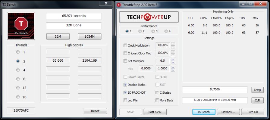
Here's the TS Bench using an M11xR1 SU7300 OC'd @ 1.6Ghz BIOS A05 and running Integrated GPU (not NVIDIA)
Two 32M runs
1. 65.660
2. 65.971
One 1024M run
1. 2104.169
For once I don't feel bad that I'm a good few seconds slower than your 2.07Ghz M11xR1
I see my M11xR1 SU7300 OC'd 1.6Ghz runs about 8C cooler than a 'super' clocked 2.07Ghz M11xR1 as 1024M test took approx. 35.06 minutes to run with CPU at 100%.
Update: I should be good and add CPU/GPU environment at the time of testing.
Update(2): Just did a couple more runs of TS Bench 32M with Nvidia enabled and the results were no better at approx. 66.288 seconds.
Well you never know, someone could have invented CPU offloading to GPU ahead of time... on DX10.1 card... from Dell...Ok....Attached Files:
-
-
Ha ha ha, with those numbers and the GPU and memory clocks pushed out a bit more, you could easily get the 3DMark06 high score for the M11xR1.
Think its was only around 7100.
Gosh, doesn't that alone make all your hard work worth while.
I'm soooooo tick'd off cause I can't get over 7000.
-
davy if you do a volt mod on the voltage regulator let us know! it might be the same design for the R2 users. it would be possible to bump the GPU voltage as well by toying with the voltage regulator yes?
-
What is the high score for M11x R1? I can go further with my GPU overclock, so that is not the end!
I doubt we'll have the same voltmod- I'm going after a VID mod on the pins of the CPU's reverse side.
I think the GPU would have it's own voltage regulator, as that is how it works on the desktop. We can already view the VID for the GPU, just not change it in any software.
EDIT: BTW, here is the overnight run of Prime95:
![[IMG]](images/storyImages/p952070.th.png)
Uploaded with ImageShack.us -
Hey guys, I found the voltage regulator- it's an Intersil 40pin ISL6261. I had a look at the pinout and I see there are FB and VID pins on it.
What exactly am I supposed to do now? I only need 1.0v for now.
Tassadar898, since I don't have a camera on me, I will draw you a paint image of the location of this chip to see if you have it too. -
awesome, thanks, ill tear apart my laptop tomorrow, i need to clean the fan anywas
-
i read this:
How voltage modding works. Can't find a voltage mod guide? Read here! - Overclockers Forums
its very old so use it with a grain of salt but you need to manipulate the FB (feedback) which according to the pinout it is pin 10. -
double posted
-
Here is the image:
![[IMG]](images/storyImages/m11xmotherboard.th.jpg)
Uploaded with ImageShack.us
I'll take a look at that article. Was really hoping for less soldering this time around like a pencil mod or conductive pen connection.
-
damn i can already tell you that the R2 is different just from this picture:
ImageShack® - Online Photo and Video Hosting
ill check tomorrow to see if the voltage regulator is different. actually i may order some arctic silver 5 and wait until that comes so I can kill two birds with one stone. -
![[IMG]](images/storyImages/vidmodssu7300.jpg)
I've guestimated your voltage range table.
Can see that if you jumper VID3+Vss the Vcc for those entries in RED will have +0.1V added. If jumper VID2+Vss then the Vcc for the entries in BLUE will be increased by 0.05V.
For NON-OC mode
You only need VID2+Vss to get you to 1.0V, that's in non-OC mode.
You'd need VID4+Vss (+0.2V) to get 1.1V in OC-mode.
You'd need VID4+Vss (+0.2V) and VID3+Vcc(-0.1V) to get 1.0V in OC-mode.
Vss=0=GND
Vcc=1=3.3V
M11x clock generator ICS9LPRS387BKLF
Discussion in 'Alienware M11x' started by duffyanneal, Feb 26, 2010.


![[IMG]](http://img402.imageshack.us/i/2070.png/)
![[IMG]](http://img703.imageshack.us/i/tsbench16.png/)
![[IMG]](http://img137.imageshack.us/i/tsbench.jpg/)
![[IMG]](http://img228.imageshack.us/i/60416574.jpg/)
![[IMG]](http://img340.imageshack.us/i/3dm0616.png/)
![[IMG]](http://img602.imageshack.us/i/3dm062070.png/)


![[IMG]](http://img843.imageshack.us/i/3dm06stock768.png/)
![[IMG]](http://img41.imageshack.us/i/3dm06ocgpu768.jpg/)
![[IMG]](http://img192.imageshack.us/i/p952070.png/)
![[IMG]](http://img694.imageshack.us/i/m11xmotherboard.jpg/)