Update: With the reprogrammed EEPROM and modded LVDS cable the M18xR2 booted up this morning like Windows 10 had never been spawned from the pits of Redmond.
I think checking the WEV is a great idea. I believe the writing process cancer might be taking place metastasizing during shutdown or POST, outside of the Windows environment, but logs may have something interesting and valuable, especially if the process or command is happening within Windows. The beast is running 344.75 drivers released in November of 2014, (which have no throttling cancer,) so it would be unexpected for NVIDIA drivers to be involved. Those are the drivers that were installed when the screen first bricked and that's why I am skeptical that NVIDIA is guilty. I believe the crosshairs belong on Micro$hift's forehead.
What commands are you using, and in what folder are you running the terminal? I ask because the i2ctools commands refused to work for me over LVDS. Only edid-rw worked, but the terminal had to be open in the folder where I unzipped edid-rw and write-edid for the display to be enumerated.
If you haven't already tried it, open a terminal window where you unzipped edid-rw and run sudo ./edid-rw 0 | edid-decode and sudo ./edid-rw 1 | edid-decode and see if either of them return information as shown in the spoiler below.
LCD not found enumerated as display #0
LCD found enumerated as display #1Code:mint@mint ~/Downloads/edid-rw-master $ sudo ./edid-rw 0 | edid-decode Traceback (most recent call last): File "./edid-rw", line 141, in <module> main() File "./edid-rw", line 129, in main edid = [dev.read(i) for i in range(EDID_HDR)] File "./edid-rw", line 48, in read return self.smb.read_byte_data(EDID_ADDR, n) IOError: [Errno 6] No such device or address Extracted contents: header: 00 00 00 00 00 00 00 00 serial number: 00 00 00 00 00 00 00 00 00 00 version: 00 00 basic params: 00 00 00 00 00 chroma info: 00 00 00 00 00 00 00 00 00 00 established: 00 00 00 standard: 00 00 00 00 00 00 00 00 00 00 00 00 00 00 00 00 descriptor 1: 00 00 00 00 00 00 00 00 00 00 00 00 00 00 00 00 00 00 descriptor 2: 00 00 00 00 00 00 00 00 00 00 00 00 00 00 00 00 00 00 descriptor 3: 00 00 00 00 00 00 00 00 00 00 00 00 00 00 00 00 00 00 descriptor 4: 00 00 00 00 00 00 00 00 00 00 00 00 00 00 00 00 00 00 extensions: 00 checksum: 00 No header found Manufacturer: @@@ Model 0 Serial Number 0 EDID version: 0.0 Analog display, Input voltage level: 0.7/0.3 V Sync: Image size is variable Gamma: 1.00 Monochrome or grayscale display Established timings supported: Standard timings supported: non-conformant standard timing (0 horiz) non-conformant standard timing (0 horiz) non-conformant standard timing (0 horiz) non-conformant standard timing (0 horiz) non-conformant standard timing (0 horiz) non-conformant standard timing (0 horiz) non-conformant standard timing (0 horiz) non-conformant standard timing (0 horiz) Manufacturer-specified data, tag 0 Manufacturer-specified data, tag 0 Manufacturer-specified data, tag 0 Manufacturer-specified data, tag 0 Checksum: 0x0 EDID block does not conform at all! Bad year of manufacture Manufacturer name field contains garbage mint@mint ~/Downloads/edid-rw-master $
Code:mint@mint ~/Downloads/edid-rw-master $ sudo ./edid-rw 1 | edid-decode Extracted contents: header: 00 ff ff ff ff ff ff 00 serial number: 4c a3 48 54 00 00 00 00 00 14 version: 01 04 basic params: 90 29 17 78 0a chroma info: c8 95 9e 57 54 92 26 0f 50 54 established: 00 00 00 standard: 01 01 01 01 01 01 01 01 01 01 01 01 01 01 01 01 descriptor 1: 29 36 80 a0 70 38 1f 40 18 10 25 00 99 e6 10 00 00 1a descriptor 2: 1c 24 80 a0 70 38 1f 40 18 10 25 00 99 e6 10 00 00 1a descriptor 3: 00 00 00 fe 00 48 47 54 33 4a 80 31 38 34 48 54 0a 20 descriptor 4: 00 00 00 00 00 00 41 01 9e 00 00 00 00 02 01 0a 20 20 extensions: 00 checksum: a8 Manufacturer: SEC Model 5448 Serial Number 0 Made week 0 of 2010 EDID version: 1.4 Digital display 6 bits per primary color channel Digital interface is not defined Maximum image size: 41 cm x 23 cm Gamma: 2.20 Supported color formats: RGB 4:4:4, YCrCb 4:2:2 First detailed timing is preferred timing Established timings supported: Standard timings supported: Detailed mode: Clock 138.650 MHz, 409 mm x 230 mm 1920 1944 1960 2080 hborder 0 1080 1082 1087 1111 vborder 0 +hsync -vsync Detailed mode: Clock 92.440 MHz, 409 mm x 230 mm 1920 1944 1960 2080 hborder 0 1080 1082 1087 1111 vborder 0 +hsync -vsync ASCII string: HGT3J�184HT Manufacturer-specified data, tag 0 Checksum: 0xa8 EDID block does NOT conform to EDID 1.3! Missing name descriptor Missing monitor ranges mint@mint ~/Downloads/edid-rw-master $
-
-
I'm still not discounting Windows (now) opening up certain interfaces that NVIDIA wasn't allowed to use before. It's up for discussion who would be responsible for the mess that results.
-
@Mr. Fox @t456
Glad to hear you got the bricked display to work. That is some next level stuff you guys are doing. Way above what I could even dream of doing.
Is there a way to write protect using a line of code or is cord cutting the way to go? Is there any draw back of cutting the cord? It seems like that would way easier for most people like me to safeguard against a re-brick using a new display. Snip one wire and good to go
-
The exact same corruption pattern as with Daniel1983's panel;
-- -- -- 05 -- -- -- 05 -- -- -- 05 -- -- -- 05 -- -- --
The '05' replaced whatever value was there before and the '--' is skip (leave value as is). That's no coincidence ... maybe they're fans of Daft Punk .
Also pretty certain now that the 0x89 can be used to enable write-protect; it's '0' in this example, where it was '1' in the other. That would match the Winbond eeprom (volatile bit). Only need to verify the exact eeprom and we can calculate the hex value required.
Possible, but that display blink would not be due to writing the edid proper; doing the same thing with write-edid does not cause a blinking screen (the changes of edid are only in effect after a reboot). However, the eeprom its stored on is much, much larger than the puny 128 or 256 bytes used for the edid. This chip also contains vcom, a value that determines the backlight's voltage (roughly between 5V and 21V) and while vcom is factory-set (every panel is different), it is also writeable afterwards. Unless write-protected, of course, but we already know that this isn't so (otherwise no corruption in the fist place). Any value that is even a little off from the original can either cause dimming/brightening, flickering or no image at all (if the value is less than 7 or higher than 21). Nvidia surely knows this and, by tinkering with the vcom value, it's possible to minimise additional flickering/ghosting that accompanies PSR (Panel Self Refresh) and/or G-Sync (same technology).
What are the pros/cons of LightBoost?
Main Pros:
+ Elimination of motion blur. CRT perfect clarity motion.
+ Improved competitive advantage by faster human reaction times.
+ Far more fluid than regular 120Hz or 144Hz.
+ Fast motion is more immersive.
Main Cons:
– Reduced brightness.
– Degradation of color quality.
– Flicker, if you are flicker sensitive.
– Requires a powerful GPU to get full benefits.
CONFIRMED: nVidia G-SYNC includes a strobe backlight upgrade!
“We have a superior, low-persistence mode that should outperform that unofficial [LightBoost] implementation, and importantly, it will be available on every G-SYNC monitor.
This scientifically confirms strobing is used, because of law of physics related to display persistence, there is no other way to do LightBoost-matching low-persistence modes without ultrahigh refresh rates (e.g. 1000fps@1000Hz) or frame interpolation (e.g. 200fps->1000fps). Since both are unlikely with nVidia G-SYNC, this officially confirms backlight strobing. In addition, John Carmack confirmed on twitter a better backlight strobe driver is included:
John Carmack (@ID_AA_Carmack) tweeted:
“@GuerillaDawg the didn’t talk about it, but this includes an improved lightboost driver, but it is currently a choice — gsync or flashed.”
Both statements by Andy and John, are confirmations that official backlight strobing (LightBoost) is part of G-SYNC, a 2D motion blur elimination, finally officially sanctioned by nVidia. The question becomes: Can both be combined into adaptive-rate backlight strobing without visible flicker?
Both are referring to external monitors only, but the lcds inside are the same; this technology applies to every lcd, whatever the plastic container they're placed in.
Now, here's the gist; the first three drawbacks of LightBoost can be ameliorated by changing vcom dynamically (remember also the 'higher brightness with 10'). That's fine and all, but the DDC specifications make clear that when writing over the DDC I2C bus you should have a minimum 30ms pause between each write. Thus; 1,000 ms / 30 ms = 33x per second, meaning that you can change vcom once every two frames with 60Hz or once every four frames with 120Hz. If they haven't taken that into account then it's also clear why eDP is generally safe; due to higher frequencies over the edid pin it's far less susceptible. But not immune; all affected eDPs were 120Hz, so the vcom change would be twice as fast as well.
To proof (or disproof) that theory:
- find vcom (same bus, different address; run sudo i2cdetect 6 <- if 6 = display bus)
- change its value a tiny bit (no harm)
- install drivers
- read-out vcom
NVIDIA CORPORATE HEADQUARTERS
2701 San Tomas Expressway
Santa Clara, CA 95050 -
Just a quick message but i fixed it too, i will edit the details in later
but i used Mr. fox approach with a old Compal NB
Gesendet von meinem Nexus 5
Edit Time: Ok like i said i will write a somewhat mini report of my case. First i started with my 771ZM itself but Linux didn't find any SMBUS/I2C Controllers attached (i guess due to no Z97 drivers? or custom Chip used in the Notebook itself + no nvidia drivers (used nomodeset to get a screen on the HDMI Display) so i thought maybe i have a old notebook lying around at work, cause i only have to get the EDID into the display and boom i'm done (at least i hoped it would be that easy, and some sort of ... it was).
First shoutout and big thx to @t456 and @Mr. Fox, you guys are my heroes.
Okay let's continue, first i found a P170SM and there Linux was actually recognizing the IC-i801 but couldn't parse information (used the Guide from @t456 from page 150). I was bit puzzled so i just guessed it is somewhat the same case as my P771ZM, and turned the machine back off.
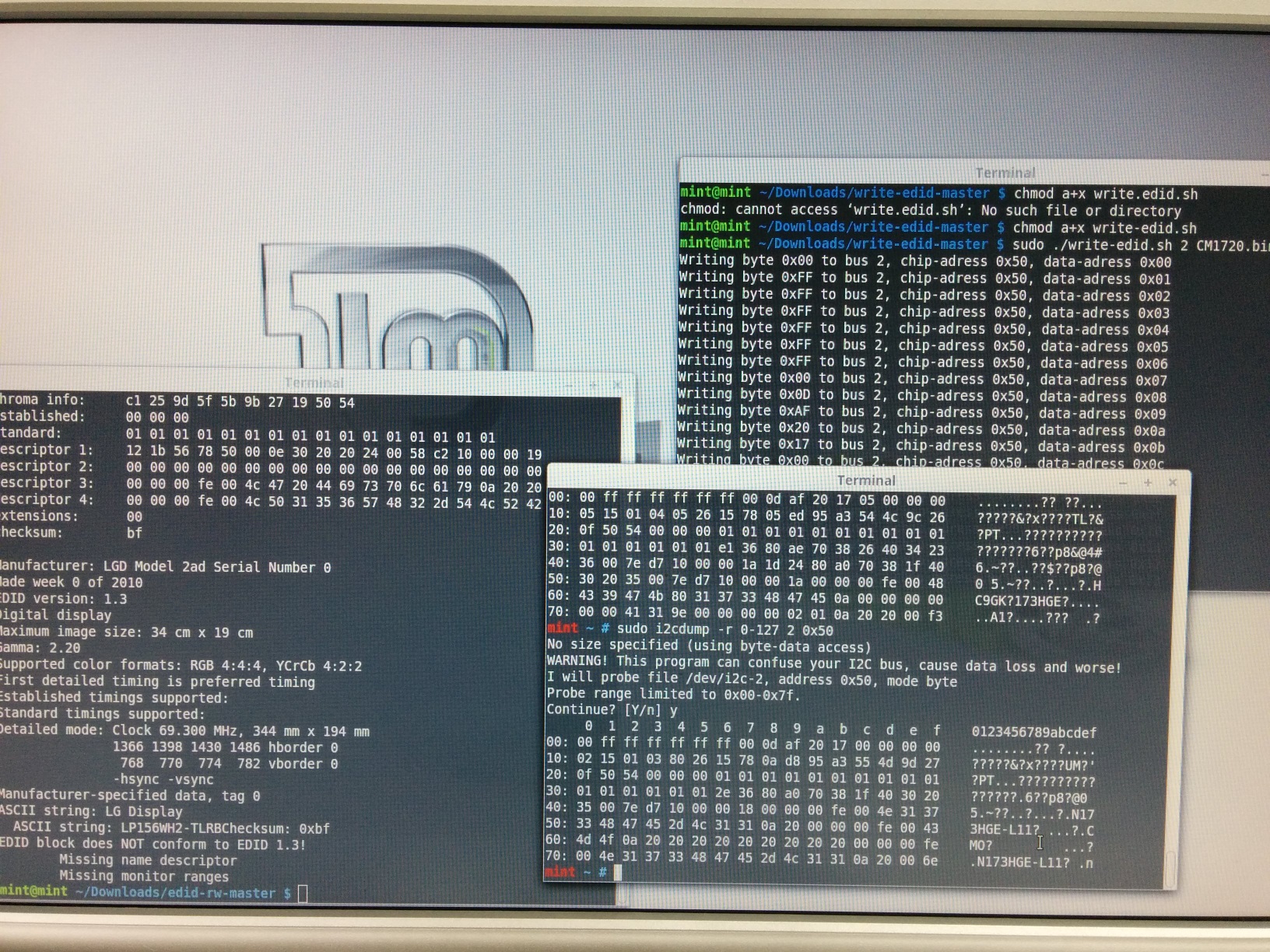
Then i was looking around and found a Compal PBL21 which was a Sandy Bridge notebook with a 520m(?) and no Optimus, didn't waited that long and did the sensor check, and boom 2 things found again the IC-i801 and a noveau sensor (dunno, but i know it was the open source nvidia driver). Didn't screened it but there were about 9-10 entries pointing to the noveau sensors after using sudo i2cdetect -l so i started getting things done quick and dumped every entry, and lo and behold i got EDID from the internal LG Panel on bus(?) 2.
I then used the steps @Mr. Fox used to doublecheck the EDID with sudo ./edid-rw 2 | edid-decode and got the LG Panel, green light. Copied over my CMO1720.bin i got yesterday into the write-edid folder, and for security reasons i plugged in a VGA display do get 2 screens, just for security, of course i tripple checked the EDID then again to be sure i don't somehow overwrite the VGA Display EDID, i knew it won't happen that the i2c bus get's changed but safety. Yeah i pulled the terminals over to the second screen, hot plugged my defective display into the Compal and of course i didn't get anything displayed at all but it didn't matter, did
sudo i2cdump -r 0-127 2 0x50 again and saw the Chi Mei actually recognized but the EDID was corrupt. Didn't matter
chmod a+x write-edid.sh and
sudo ./write-edid.sh 1 CMO1720.bin let it do it's job for some seconds and boom done finished.
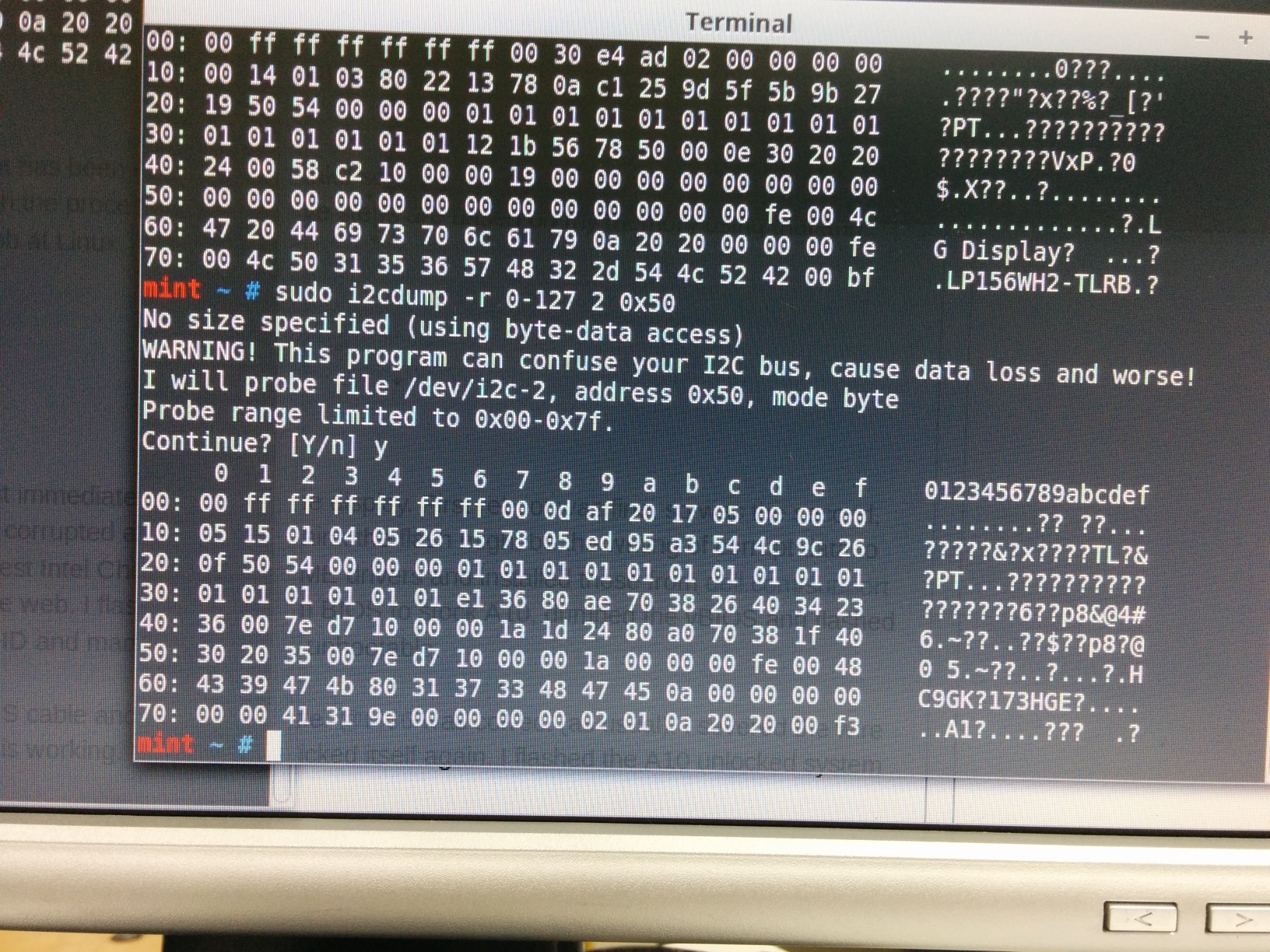
sudo i2cdump -r 0-127 2 0x50
again, looked good, hot plugged the display off, put in into my P771ZM spammed F2 and boom, bios is there again, started up Windows once and shut it off, and still to date i didn't even turned the machine back on again, but i will after about some minutes
So actually i have to reflash prema mod now and avoid(?) windows 10 for a while
Edit 2: but where was the EDID actually corrupt in which collumn?Attached Files:
Last edited: Sep 15, 2015 -
-
Maybe this can help to disclose why MS modify BIOS, well, not the bios itself, the NVRAM
http://answers.microsoft.com/en-us/...1/65d74e19-9572-4a91-85aa-57fa783f0759?auth=1
About why these modification/corruption persist even after a BIOS reflash i'll tell you my theory based in my personal experience:
At least in my desktop, sometimes when i was installing W10 TP, finish the install and some OS testing, after turning off the system (to be clear at this point w10 by default uses fastboot, so when you turn off the pc, system is not being turned off really, it's like a standby), if i cut energy in this mode, I.E turning off the power regulator or ups, when i try to turn on the system i get POST problems or even worse, the system refuse to start.
What i found when i was trying to solve that problem is that this modification/corruption is not on BIOS, it's highly probable that is on NVRAM, but here is when weird things start; at least in my case, trying to clear the nvram with the most user friendly options did not solve the problem (clrCMOS button, remove battery), so after that i´ve used the clr cmos jumper and voila, problem gone, however, so at these moment i thought that the clrcmos button was bad, however, a few days ago i wanted to confirm that and for my surprise the button is ok, when i use it my bios settings disappear, so i must ask, if the clrcmos button and the jumper are intended for the same task why the button is unable to clear all nvram, at least the part that windows modified/corrupted???
So were i want to go or what i'm trying to say?... well, could it be possible that these modifications that you report are in some way the same i've suffered?, in that case, it's possible that the methods that you are using to clear the nvram are not erasing the nvram at 100%?? just for curiosity, these laptops have a clrcmos jumper or some points on pcb intended for this procedure?
Excuse the bad english -
Do you remember when m$ was setting up to advertise win 10 as the brightest Windows yet?TomJGX, PC GAMER, andrewsi2012 and 3 others like this.
-
I know I'm going to have customers asking for win 10 soon regardless of all the issues it has.
Is cutting the LVDS wire mentioned in previous post going to bullet proof these LCD's against ANY eeprom re-writing?
If I have a 17 or 18 that has not had win 10 installed, can I safely install it after this mod? -
Would cutting 5 pin wire enable write protection for LG LP173WFI TL B3, @t456?
-
Maybe, but only if they were truly incompetent ... and that'd only apply with certainty to the SEC5448. The others would have to be tested similarly. @Mr. Fox can check this by using write-edid again, except this time with a slightly different edid and see if the change is effective. Made an improved SEC5448 edid (which contains the full panel nr., instead of Dell's part id.):
SEC5448 (LTN184HT02-S01) - panel nr.7z
![[IMG]](images/storyImages/EwSFv.png)
It's a win-win; if it doesn't stick then you've found an easy write-protect. And if it does stick then you've changed it to the correct, actual panel number .
Mr. Fox likes this.
.
Mr. Fox likes this. -
I will test it later today or tomorrow. I have two more spare LVDS cables and another bricked panel sitting here that I can chop the fourth wire from the right for LVDS pin #5 on one of them and see if Linux will let me flash the new/improved EDID, or if I have to swap over the cable that has not been modded in order to write the new EDID. Will report back what I find after I do that. I've reassembled the M18xR2 so I can use it as normal to see if the fix is truly permanent. So far, so good.
@t456 - thanks for fixing that EDID also.
Agree with @t456 - uncertain at this point. What works for the M18xR1/R2 LVDS setup may not work on another model. If you are trying to do the same thing on an M17xR3/R4, AW17 and AW18 it may not work. If my testing later today or tomorrow reveals I cannot flash the EDID with the cut cable, you would likely still need to source a spare LVDS cable for the specific model in question and use it as a guinea pig if you don't have a schematic to answer the question. These displays are apparently not all cross compatible. The new PLS display and LVDS cable that I have for the AW18 will not do anything when attached to the M18xR1 or M18xR2. The display never lights up at all. I had tested this a while back (maybe a year ago) on the Alienware 18 and M18xR2 and neither display would work connected to the other machine for some reason. Black screen, no backlight, even during POST (but no 8 beeps) so maybe the pin-out configuration is different for the AW18 PLS panel. If you have any M18xR1/R2 and any M17xR3/R4 with 60Hz displays, you might try swapping the panels to see if both will work on the opposite machine. If both work, then there is a good chance that snipping the wire will work the same on any of those four notebook models.
I don't have any spare parts for the AW18, so I am not able to do any experimenting. When the programmer I ordered from China arrives I am going to dump the EDID.bin from the brand new PLS panel I have here so we will have that for the archive @t456 has put together. I will also need it for disaster recovery if the AW18 re-bricks the new panel. I'm not going to do any testing with the AW18 until I have the programmer. -
I was asking an Alienware rep for help on my desktop on twitter (Alienware support) and when I followed up with a question about using windows 10 with my Alienware 18, he said that they have not had any problems and that it should work fine
TomJGX, PC GAMER and andrewsi2012 like this. -
Does this look ok? Screen was not found using 0 or 1, but the command worked using 2. Is there anything I should change? This is my only screen, which was flashed and never touched by any nvidia driver after the last flashing as a safety precaution.
mint@mint ~/Downloads/edid-rw-master $ sudo ./edid-rw 2 | edid-decode
Extracted contents:
header: 00 ff ff ff ff ff ff 00
serial number: 30 e4 da 02 00 00 00 00 00 14
version: 01 04
basic params: 90 26 16 78 0a
chroma info: f1 95 a3 55 52 a1 26 0f 50 54
established: 00 00 00
standard: 01 01 01 01 01 01 01 01 01 01 01 01 01 01 01 01
descriptor 1: b0 36 80 b0 70 38 21 40 30 20 35 00 7c dc 10 00 00 18
descriptor 2: 75 24 80 b0 70 38 21 40 30 20 35 00 7c dc 10 00 00 18
descriptor 3: 00 00 00 fe 00 4d 47 4e 43 37 80 31 37 33 57 46 31 0a
descriptor 4: 00 00 00 00 00 00 41 31 9e 00 00 00 00 02 01 0a 20 20
extensions: 00
checksum: b0
Manufacturer: LGD Model 2da Serial Number 0
Made week 0 of 2010
EDID version: 1.4
Digital display
6 bits per primary color channel
Digital interface is not defined
Maximum image size: 38 cm x 22 cm
Gamma: 2.20
Supported color formats: RGB 4:4:4, YCrCb 4:2:2
First detailed timing is preferred timing
Established timings supported:
Standard timings supported:
Detailed mode: Clock 140.000 MHz, 380 mm x 220 mm
1920 1968 2000 2096 hborder 0
1080 1083 1088 1113 vborder 0
-hsync -vsync
Detailed mode: Clock 93.330 MHz, 380 mm x 220 mm
1920 1968 2000 2096 hborder 0
1080 1083 1088 1113 vborder 0
-hsync -vsync
ASCII string: MGNC7�173WF1
Manufacturer-specified data, tag 0
Checksum: 0xb0
EDID block does NOT conform to EDID 1.3!
   Missing name descriptor
Missing monitor ranges Last edited: Sep 15, 2015ajc9988 likes this.
 -
Looks correct to me.
If the checksum were wrong it would say so. The other info at the bottom is what I saw. The panel is EDID 1.4 and it appears the messaging at the bottom applies to EDID 1.3 standards, but I am not 100% certain about how that works.
Code:Checksum: 0xb0 EDID block does NOT conform to EDID 1.3! Missing name descriptor Missing monitor ranges
mariussx likes this. -
Well, that's certainly unfortunate misinformation. I suspect the person that said that is totally unaware of the situation. Since the Dell Drivers and Downloads Support page for the Alienware 18 shows drivers for Windows 10, it's say it's a logical response from a social media rep that simply doesn't know about the danger. I'm surprised they haven't pulled all of the Windows 10 drivers and posted a warning on the Drivers and Downloads web site.TomJGX, PC GAMER, andrewsi2012 and 1 other person like this.
-
' Monitor Range Limits' applies to GTF timing only, this was superseded by CVT with E-EDID v1.4. With a v1.4 edid this message is normal. The ' missing name descriptor' is Dell's handiwork, the slightly adjusted SEC5448 should not show that message.
The LP173WF1-TLB3 is indeed fine ... so far. Without knowing the actual eeprom for that panel, better search for the write-protect bit's location on the I2C bus.
Actually ... it does change. Upon every boot the I2C buses are re-enumerated (my panel is either on 6 or 18, so far). Have amended the instructions to warn of that possibility:
Code:start 01 check 'pnp id -panel nrs.txt' for the correct bin 02 copy it to the 'write-edid' folder 03 open terminal (ctr+alt+T) 04 sudo bash 05 sudo sensors-detect Hit 'n' for all 'YES/no' questions, EXCEPT I2C/SMBus, hit 'y' for that. There'll be something like 'Using driver 'i2c-XYZ' <- mine was i2c-i801 (Lynx Point), hit 'n' for the remaining questions. 06 sudo modprobe i2c-XYZ (i2c-i801 for me) 07 sudo modprobe i2c-dev 08 sudo i2cdetect -l result: ###################################### root@it:~# sudo i2cdetect -l i2c-0 i2c i915 gmbus ssc I2C adapter i2c-1 i2c i915 gmbus vga I2C adapter i2c-2 i2c i915 gmbus panel I2C adapter i2c-3 i2c i915 gmbus dpc I2C adapter i2c-4 i2c i915 gmbus dpb I2C adapter i2c-5 i2c i915 gmbus dpd I2C adapter i2c-6 i2c DPDDC-A I2C adapter i2c-7 i2c DPDDC-C I2C adapter i2c-8 i2c nouveau-0000:01:00.0-0 I2C adapter i2c-9 i2c nouveau-0000:01:00.0-1 I2C adapter i2c-10 i2c nouveau-0000:01:00.0-2 I2C adapter i2c-11 i2c nouveau-0000:01:00.0-5 I2C adapter i2c-12 i2c nouveau-0000:01:00.0-6 I2C adapter i2c-13 i2c nouveau-0000:01:00.0-7 I2C adapter i2c-14 i2c nouveau-0000:01:00.0-8 I2C adapter i2c-15 i2c nouveau-0000:01:00.0-9 I2C adapter i2c-16 i2c nouveau-0000:01:00.0-26 I2C adapter i2c-17 i2c nouveau-0000:01:00.0-27 I2C adapter i2c-18 i2c nouveau-0000:01:00.0-28 I2C adapter i2c-19 i2c nouveau-0000:01:00.0-29 I2C adapter root@it:~# ###################################### If, for whatever reason, you have restarted/rebooted AFTER running 'i2cdetect -l'; ALWAYS RE-RUN THAT COMMAND before asssuming the edid will be on the same bus. The bus enumeration is usually fixed, but not always so; make CERTAIN you have the right bus. Those 0-19 are the list of buses, now we need to find out which bus the panel is on. It could be 'panel' (bus 2), but one the 'DPDDC's is also possible. Let's try bus 2 first. we read (-r) the bytes 0 to 127, so 128 bytes in total, and we check this bus 2 at address 50 <- this SHOULD contain the edid, BUT-T-T-T ... that is not guaranteed -> IF it is on a different address then either the read part or, especially, the writing part can change things that are hard to fix. We're not interested in the difference between 128 byte or 256 byte edids yet, so extracting the first 128 bytes will do for now. 09 sudo i2cdump -r 0-127 2 0x50 result: ###################################### root@it:~# sudo i2cdump -r 0-127 2 0x50 No size specified (using byte-data access) WARNING! This program can confuse your I2C bus, cause data loss and worse! I will probe file /dev/i2c-2, address 0x50, mode byte Probe range limited to 0x00-0x7f. Continue? [Y/n] y 0 1 2 3 4 5 6 7 8 9 a b c d e f 0123456789abcdef 00: XX XX XX XX XX XX XX XX XX XX XX XX XX XX XX XX XXXXXXXXXXXXXXXX 10: XX XX XX XX XX XX XX XX XX XX XX XX XX XX XX XX XXXXXXXXXXXXXXXX 20: XX XX XX XX XX XX XX XX XX XX XX XX XX XX XX XX XXXXXXXXXXXXXXXX 30: XX XX XX XX XX XX XX XX XX XX XX XX XX XX XX XX XXXXXXXXXXXXXXXX 40: XX XX XX XX XX XX XX XX XX XX XX XX XX XX XX XX XXXXXXXXXXXXXXXX 50: XX XX XX XX XX XX XX XX XX XX XX XX XX XX XX XX XXXXXXXXXXXXXXXX 60: XX XX XX XX XX XX XX XX XX XX XX XX XX XX XX XX XXXXXXXXXXXXXXXX 70: XX XX XX XX XX XX XX XX XX XX XX XX XX XX XX XX XXXXXXXXXXXXXXXX root@it:~# ###################################### So the edid is not here. If it was the edid then you'll see the '00 FF FF FF FF FF FF 00' start header, even if a little corrupted. If you find that then you know the bus AND the address. Anyway, let's try bus 6 next (DPDDC-A). 09 sudo i2cdump -r 0-127 6 0x50 result: ###################################### 0 1 2 3 4 5 6 7 8 9 a b c d e f 0123456789abcdef 00: 00 ff ff ff ff ff ff 00 4d 10 ff 13 00 00 00 00 ........M?.?.... 10: 00 17 01 04 a5 1d 11 78 06 de 50 a3 54 4c 99 26 .??????x??P?TL?& 20: 0f 50 54 00 00 00 01 01 01 01 01 01 01 01 01 01 ?PT...?????????? 30: 01 01 01 01 01 01 56 5e 00 a0 a0 a0 29 50 30 20 ??????V^.???)P0 40: 35 00 26 a5 10 00 00 18 00 00 00 10 00 00 00 00 5.&??..?...?.... 50: 00 00 00 00 00 00 00 00 00 00 00 00 00 10 00 00 .............?.. 60: 00 00 00 00 00 00 00 00 00 00 00 00 00 00 00 fc ...............? 70: 00 4c 51 31 33 33 54 31 4a 57 30 32 0a 20 00 b0 .LQ133T1JW02? .? ###################################### Good, bus 6 it is. Now pay attention to byte 7e. Read address like it was excel: ROW-COLUMN. In this example 7e = 00 (zero) and it's in-between values 20 and b0. The b0 is the final bit (and checksum), if 7e = 01 (one) then you have an extension block and require a 256 byte edid. These are also availeable the archive, but the difference is that you need to use 'write-edid-256.sh' instead of 'write-edid.sh'. Let's make an export to verify actual corruption first and also to help further research: 09 sudo i2cdump -r 0-127 6 0x50 > EDID/edidexport.txt Or, if case you have a 256 byte edid: 09 sudo i2cdump -r 0-255 6 0x50 > EDID/edidexport.txt Check the export by opening the .txt and copy/pasting the significant hex values to the Web Based EDID Reader website. The pasted values should be stripped of row and column id and the ascii characters to the right: example: ###################################### 00 ff ff ff ff ff ff 00 4d 10 ff 13 00 00 00 00 00 17 01 04 a5 1d 11 78 06 de 50 a3 54 4c 99 26 0f 50 54 00 00 00 01 01 01 01 01 01 01 01 01 01 01 01 01 01 01 01 56 5e 00 a0 a0 a0 29 50 30 20 35 00 26 a5 10 00 00 18 00 00 00 10 00 00 00 00 00 00 00 00 00 00 00 00 00 00 00 00 00 10 00 00 00 00 00 00 00 00 00 00 00 00 00 00 00 00 00 fc 00 4c 51 31 33 33 54 31 4a 57 30 32 0a 20 00 b0 ###################################### If the EDID Reader says 'checksum valid' then do not proceed any further; the edid is fine and, thus, something else must be wrong ... If it says 'checksum fail' AND you have your bus AND address by now; skip the stuff below and proceed to step 10. If, on the other hand, you received all XX on all buses then 50 is not the right address for you ... we need to look beyond 50: 09 sudo i2cdetect 6 result: ###################################### root@it:~# sudo i2cdetect 6 WARNING! This program can confuse your I2C bus, cause data loss and worse! I will probe file /dev/i2c-6. I will probe address range 0x03-0x77. Continue? [Y/n] y 0 1 2 3 4 5 6 7 8 9 a b c d e f 00: -- -- -- -- -- -- -- -- -- -- -- -- -- 10: -- 11 -- -- -- -- -- -- -- -- -- -- -- -- -- -- 20: -- -- -- -- -- -- -- -- -- -- -- -- -- -- -- -- 30: -- -- -- -- -- -- -- -- -- -- -- -- -- -- -- -- 40: -- -- -- -- -- -- -- -- -- -- -- -- -- -- -- -- 50: 50 -- -- -- -- -- -- -- -- -- -- -- -- -- -- -- 60: -- -- -- -- -- -- -- -- -- -- -- -- -- -- -- -- 70: -- -- -- -- -- -- -- -- root@it:~# ###################################### So there IS something else here besides the edid at 50 ... Wonder what that button does ... Anyway; go back to the beginning of step 9 and redo the 'read bus', only this time at address 11 (or whatever your results were). ###################################### 10 cd EDID/edid-rw At this point we should have: - BUS (here 6) - ADDRESS (here 50) - EDID LENGTH 128 or 256 (here 128). 11 sudo ./edid-rw 6 | edid-decode This is just a precaution; we want to make sure edid-rw uses the right address, if not then we need to change its code (report this if so). result: ###################################### root@it:~/EDID/edid-rw# sudo ./edid-rw 6 | edid-decode Extracted contents: header: 00 ff ff ff ff ff ff 00 serial number: 4d 10 ff 13 00 00 00 00 00 17 version: 01 04 basic params: a5 1d 11 78 06 chroma info: de 50 a3 54 4c 99 26 0f 50 54 established: 00 00 00 standard: 01 01 01 01 01 01 01 01 01 01 01 01 01 01 01 01 descriptor 1: 56 5e 00 a0 a0 a0 29 50 30 20 35 00 26 a5 10 00 00 18 descriptor 2: 00 00 00 10 00 00 00 00 00 00 00 00 00 00 00 00 00 00 descriptor 3: 00 00 00 10 00 00 00 00 00 00 00 00 00 00 00 00 00 00 descriptor 4: 00 00 00 fc 00 4c 51 31 33 33 54 31 4a 57 30 32 0a 20 extensions: 00 checksum: b0 Manufacturer: SHP Model 13ff Serial Number 0 Made week 0 of 2013 EDID version: 1.4 Digital display 8 bits per primary color channel DisplayPort interface Maximum image size: 29 cm x 17 cm Gamma: 2.20 Supported color formats: RGB 4:4:4 Default (sRGB) color space is primary color space First detailed timing is preferred timing Established timings supported: Standard timings supported: Detailed mode: Clock 241.500 MHz, 294 mm x 165 mm 2560 2608 2640 2720 hborder 0 1440 1443 1448 1481 vborder 0 -hsync -vsync Dummy block Dummy block Monitor name: LQ133T1JW02 Checksum: 0xb0 EDID block does NOT conform to EDID 1.3! Missing monitor ranges root@it:~/EDID/edid-rw# ###################################### Good, so we're looking at the same thing. If you've made it this far then we're pretty much finished. IF you have an edid address different from 50, then we need to change the write-edid.sh script accordingly (report this). If it is the standard address 50, then proceed: Let's rewrite the edid (the .bin you copied to the 'write-edid' folder). We'll presume it's called ABCDEF.bin. The actual tool it uses is i2cset (docs bookmarked), but this writes byte-for-byte, whereas the write-edid.sh script automates that (with address=50 pre-set). 12 cd .. 13 cd write-edid 14 sudo bash ./write-edid.sh 6 ABCDEF.bin result: ###################################### root@it:~/EDID/write-edid# sudo bash ./write-edid.sh 6 SHP13FFmod.bin Writing byte 0x00 to bus 6, chip-adress 0x50, data-adress 0x00 Writing byte 0xFF to bus 6, chip-adress 0x50, data-adress 0x01 Writing byte 0xFF to bus 6, chip-adress 0x50, data-adress 0x02 Writing byte 0xFF to bus 6, chip-adress 0x50, data-adress 0x03 Writing byte 0xFF to bus 6, chip-adress 0x50, data-adress 0x04 Writing byte 0xFF to bus 6, chip-adress 0x50, data-adress 0x05 Writing byte 0xFF to bus 6, chip-adress 0x50, data-adress 0x06 Writing byte 0x00 to bus 6, chip-adress 0x50, data-adress 0x07 Writing byte 0x30 to bus 6, chip-adress 0x50, data-adress 0x08 Writing byte 0xE4 to bus 6, chip-adress 0x50, data-adress 0x09 Writing byte 0x6C to bus 6, chip-adress 0x50, data-adress 0x0a Writing byte 0x04 to bus 6, chip-adress 0x50, data-adress 0x0b Writing byte 0x00 to bus 6, chip-adress 0x50, data-adress 0x0c Writing byte 0x00 to bus 6, chip-adress 0x50, data-adress 0x0d Writing byte 0x00 to bus 6, chip-adress 0x50, data-adress 0x0e Writing byte 0x00 to bus 6, chip-adress 0x50, data-adress 0x0f Writing byte 0x00 to bus 6, chip-adress 0x50, data-adress 0x10 Writing byte 0x18 to bus 6, chip-adress 0x50, data-adress 0x11 Writing byte 0x01 to bus 6, chip-adress 0x50, data-adress 0x12 Writing byte 0x04 to bus 6, chip-adress 0x50, data-adress 0x13 Writing byte 0xA5 to bus 6, chip-adress 0x50, data-adress 0x14 Writing byte 0x1D to bus 6, chip-adress 0x50, data-adress 0x15 Writing byte 0x11 to bus 6, chip-adress 0x50, data-adress 0x16 Writing byte 0x78 to bus 6, chip-adress 0x50, data-adress 0x17 Writing byte 0x06 to bus 6, chip-adress 0x50, data-adress 0x18 Writing byte 0xDE to bus 6, chip-adress 0x50, data-adress 0x19 Writing byte 0x50 to bus 6, chip-adress 0x50, data-adress 0x1a Writing byte 0xA3 to bus 6, chip-adress 0x50, data-adress 0x1b Writing byte 0x54 to bus 6, chip-adress 0x50, data-adress 0x1c Writing byte 0x4C to bus 6, chip-adress 0x50, data-adress 0x1d Writing byte 0x99 to bus 6, chip-adress 0x50, data-adress 0x1e Writing byte 0x26 to bus 6, chip-adress 0x50, data-adress 0x1f Writing byte 0x0F to bus 6, chip-adress 0x50, data-adress 0x20 Writing byte 0x50 to bus 6, chip-adress 0x50, data-adress 0x21 Writing byte 0x54 to bus 6, chip-adress 0x50, data-adress 0x22 Writing byte 0x00 to bus 6, chip-adress 0x50, data-adress 0x23 Writing byte 0x00 to bus 6, chip-adress 0x50, data-adress 0x24 Writing byte 0x00 to bus 6, chip-adress 0x50, data-adress 0x25 Writing byte 0x01 to bus 6, chip-adress 0x50, data-adress 0x26 Writing byte 0x01 to bus 6, chip-adress 0x50, data-adress 0x27 Writing byte 0x01 to bus 6, chip-adress 0x50, data-adress 0x28 Writing byte 0x01 to bus 6, chip-adress 0x50, data-adress 0x29 Writing byte 0x01 to bus 6, chip-adress 0x50, data-adress 0x2a Writing byte 0x01 to bus 6, chip-adress 0x50, data-adress 0x2b Writing byte 0x01 to bus 6, chip-adress 0x50, data-adress 0x2c Writing byte 0x01 to bus 6, chip-adress 0x50, data-adress 0x2d Writing byte 0x01 to bus 6, chip-adress 0x50, data-adress 0x2e Writing byte 0x01 to bus 6, chip-adress 0x50, data-adress 0x2f Writing byte 0x01 to bus 6, chip-adress 0x50, data-adress 0x30 Writing byte 0x01 to bus 6, chip-adress 0x50, data-adress 0x31 Writing byte 0x01 to bus 6, chip-adress 0x50, data-adress 0x32 Writing byte 0x01 to bus 6, chip-adress 0x50, data-adress 0x33 Writing byte 0x01 to bus 6, chip-adress 0x50, data-adress 0x34 Writing byte 0x01 to bus 6, chip-adress 0x50, data-adress 0x35 Writing byte 0x2A to bus 6, chip-adress 0x50, data-adress 0x36 Writing byte 0x44 to bus 6, chip-adress 0x50, data-adress 0x37 Writing byte 0x80 to bus 6, chip-adress 0x50, data-adress 0x38 Writing byte 0xA0 to bus 6, chip-adress 0x50, data-adress 0x39 Writing byte 0x70 to bus 6, chip-adress 0x50, data-adress 0x3a Writing byte 0x38 to bus 6, chip-adress 0x50, data-adress 0x3b Writing byte 0x27 to bus 6, chip-adress 0x50, data-adress 0x3c Writing byte 0x40 to bus 6, chip-adress 0x50, data-adress 0x3d Writing byte 0x30 to bus 6, chip-adress 0x50, data-adress 0x3e Writing byte 0x20 to bus 6, chip-adress 0x50, data-adress 0x3f Writing byte 0x35 to bus 6, chip-adress 0x50, data-adress 0x40 Writing byte 0x00 to bus 6, chip-adress 0x50, data-adress 0x41 Writing byte 0x26 to bus 6, chip-adress 0x50, data-adress 0x42 Writing byte 0xA5 to bus 6, chip-adress 0x50, data-adress 0x43 Writing byte 0x10 to bus 6, chip-adress 0x50, data-adress 0x44 Writing byte 0x00 to bus 6, chip-adress 0x50, data-adress 0x45 Writing byte 0x00 to bus 6, chip-adress 0x50, data-adress 0x46 Writing byte 0x18 to bus 6, chip-adress 0x50, data-adress 0x47 Writing byte 0x56 to bus 6, chip-adress 0x50, data-adress 0x48 Writing byte 0x5E to bus 6, chip-adress 0x50, data-adress 0x49 Writing byte 0x00 to bus 6, chip-adress 0x50, data-adress 0x4a Writing byte 0xA0 to bus 6, chip-adress 0x50, data-adress 0x4b Writing byte 0xA0 to bus 6, chip-adress 0x50, data-adress 0x4c Writing byte 0xA0 to bus 6, chip-adress 0x50, data-adress 0x4d Writing byte 0x29 to bus 6, chip-adress 0x50, data-adress 0x4e Writing byte 0x50 to bus 6, chip-adress 0x50, data-adress 0x4f Writing byte 0x30 to bus 6, chip-adress 0x50, data-adress 0x50 Writing byte 0x20 to bus 6, chip-adress 0x50, data-adress 0x51 Writing byte 0x35 to bus 6, chip-adress 0x50, data-adress 0x52 Writing byte 0x00 to bus 6, chip-adress 0x50, data-adress 0x53 Writing byte 0x26 to bus 6, chip-adress 0x50, data-adress 0x54 Writing byte 0xA5 to bus 6, chip-adress 0x50, data-adress 0x55 Writing byte 0x10 to bus 6, chip-adress 0x50, data-adress 0x56 Writing byte 0x00 to bus 6, chip-adress 0x50, data-adress 0x57 Writing byte 0x00 to bus 6, chip-adress 0x50, data-adress 0x58 Writing byte 0x18 to bus 6, chip-adress 0x50, data-adress 0x59 Writing byte 0x00 to bus 6, chip-adress 0x50, data-adress 0x5a Writing byte 0x00 to bus 6, chip-adress 0x50, data-adress 0x5b Writing byte 0x00 to bus 6, chip-adress 0x50, data-adress 0x5c Writing byte 0xFE to bus 6, chip-adress 0x50, data-adress 0x5d Writing byte 0x00 to bus 6, chip-adress 0x50, data-adress 0x5e Writing byte 0x4C to bus 6, chip-adress 0x50, data-adress 0x5f Writing byte 0x47 to bus 6, chip-adress 0x50, data-adress 0x60 Writing byte 0x20 to bus 6, chip-adress 0x50, data-adress 0x61 Writing byte 0x44 to bus 6, chip-adress 0x50, data-adress 0x62 Writing byte 0x69 to bus 6, chip-adress 0x50, data-adress 0x63 Writing byte 0x73 to bus 6, chip-adress 0x50, data-adress 0x64 Writing byte 0x70 to bus 6, chip-adress 0x50, data-adress 0x65 Writing byte 0x6C to bus 6, chip-adress 0x50, data-adress 0x66 Writing byte 0x61 to bus 6, chip-adress 0x50, data-adress 0x67 Writing byte 0x79 to bus 6, chip-adress 0x50, data-adress 0x68 Writing byte 0x0A to bus 6, chip-adress 0x50, data-adress 0x69 Writing byte 0x20 to bus 6, chip-adress 0x50, data-adress 0x6a Writing byte 0x20 to bus 6, chip-adress 0x50, data-adress 0x6b Writing byte 0x00 to bus 6, chip-adress 0x50, data-adress 0x6c Writing byte 0x00 to bus 6, chip-adress 0x50, data-adress 0x6d Writing byte 0x00 to bus 6, chip-adress 0x50, data-adress 0x6e Writing byte 0xFE to bus 6, chip-adress 0x50, data-adress 0x6f Writing byte 0x00 to bus 6, chip-adress 0x50, data-adress 0x70 Writing byte 0x4C to bus 6, chip-adress 0x50, data-adress 0x71 Writing byte 0x50 to bus 6, chip-adress 0x50, data-adress 0x72 Writing byte 0x31 to bus 6, chip-adress 0x50, data-adress 0x73 Writing byte 0x37 to bus 6, chip-adress 0x50, data-adress 0x74 Writing byte 0x33 to bus 6, chip-adress 0x50, data-adress 0x75 Writing byte 0x57 to bus 6, chip-adress 0x50, data-adress 0x76 Writing byte 0x46 to bus 6, chip-adress 0x50, data-adress 0x77 Writing byte 0x34 to bus 6, chip-adress 0x50, data-adress 0x78 Writing byte 0x2D to bus 6, chip-adress 0x50, data-adress 0x79 Writing byte 0x53 to bus 6, chip-adress 0x50, data-adress 0x7a Writing byte 0x50 to bus 6, chip-adress 0x50, data-adress 0x7b Writing byte 0x44 to bus 6, chip-adress 0x50, data-adress 0x7c Writing byte 0x31 to bus 6, chip-adress 0x50, data-adress 0x7d Writing byte 0x00 to bus 6, chip-adress 0x50, data-adress 0x7e Writing byte 0x6B to bus 6, chip-adress 0x50, data-adress 0x7f Writing done, here is the output of i2cdump -y 6 0x50: No size specified (using byte-data access) 0 1 2 3 4 5 6 7 8 9 a b c d e f 0123456789abcdef 00: 00 ff ff ff ff ff ff 00 4d 10 ff 13 00 00 00 00 ........M?.?.... 10: 00 17 01 04 a5 1d 11 78 06 de 50 a3 54 4c 99 26 .??????x??P?TL?& 20: 0f 50 54 00 00 00 01 01 01 01 01 01 01 01 01 01 ?PT...?????????? 30: 01 01 01 01 01 01 56 5e 00 a0 a0 a0 29 50 30 20 ??????V^.???)P0 40: 35 00 26 a5 10 00 00 18 00 00 00 10 00 00 00 00 5.&??..?...?.... 50: 00 00 00 00 00 00 00 00 00 00 00 00 00 10 00 00 .............?.. 60: 00 00 00 00 00 00 00 00 00 00 00 00 00 00 00 fc ...............? 70: 00 4c 51 31 33 33 54 31 4a 57 30 32 0a 20 00 b0 .LQ133T1JW02? .? 80: 00 00 00 00 00 00 00 00 00 00 00 00 00 00 00 00 ................ 90: 00 00 00 00 00 00 00 00 00 00 00 00 00 00 00 00 ................ a0: 00 00 00 00 00 00 00 00 00 00 00 00 00 00 00 00 ................ b0: 00 00 00 00 00 00 00 00 00 00 00 00 00 00 00 00 ................ c0: 00 00 00 00 00 00 00 00 00 00 00 00 00 00 00 00 ................ d0: 00 00 00 00 00 00 00 00 00 00 00 00 00 00 00 00 ................ e0: 00 00 00 00 00 00 00 00 00 00 00 00 00 00 00 00 ................ f0: 00 00 00 00 00 00 00 00 00 00 00 00 00 00 00 00 ................ ###################################### So ... it's the same edid ... Seems my eeprom is already write-protected (unfortunately, for me; it's be 75Hz otherwise). If successful then you should have a different edid than before and your panel is fixed. There's also a vcom eeprom, but let's not get into that right now. finish
I know @Mr. Fox 's instructions are simpler, easier to read and much better formatted, but he did skip over a few safety-related remarks (ahem ). Those are of no concern if you have a run-of-the-mill configuration, but it can have consequences if:
- You've rebooted inbetween.
- The edid address is not at 0x50.
- The edid you have is not 128 bytes.
Updated archive: bricked displays, correct edids, v6
Interstella 5555 again:
![[IMG]](images/storyImages/Fnlqp.png)
You've also flashed the CRU overclock version ... (bad, bad !). Anyway, if correct, CRU can now be done away with; the 110Hz option should be available in both Intel HD and Nvidia control panel. Would you check if this is so? Kinda what I was hoping to accomplish
before the write-protected eeprom blocked that route ...
-
Thanks for the updated instructions @t456 - I'm a total noob at Linux. I stumbled my way through the process and simply got lucky. But, I would not have even attempted it had it not been for all of your helpful posts in this thread. All credit goes to you, bro.
Being an old MS-DOS fanboy and feeling totally at home with a command prompt does help reduce the intimidation level dealing with a Linux terminal. I was pretty much anti-Windows until Windows 98 SE and up through Win2K I thought real men always used a command prompt. Looks like their latest OS abortion stands a chance of making me anti-Windows again. -
Exactly so, that's why Secure Boot = rootkit.
Possible methods used:
1.) It accomplish this by changing the nvram index to make its nvram sectors non-nvram. Any process that relies on that index would now skip those sectors; even the cmos battery appears to sail by that. The reason the jumper works is that this wipes nvram by high voltage (shorting) and this would happily ignore whatever a marker or index says is nvram.
2.) It changes one of the Block Protect bits to read-only, safeguarding it from a wipe command. Pulling the battery would not change that bit since this requires high voltage. The bridge/short does exactly that, so it can flip the BP bits:
![[IMG]](images/storyImages/BZisT.png)
Think that if you know how the LoJack module works (also a rootkit, imo), then you know how Secure Boot operates as well.
That information should scare the bejesus out of anyone ...
and would backup the persistent bios change theory.
PC GAMER, ajc9988, andrewsi2012 and 1 other person like this.
...
and would backup the persistent bios change theory.
PC GAMER, ajc9988, andrewsi2012 and 1 other person like this. -
Don't worry, only dallying around myself. Just can't accept an ' error #7'; search, read, search etc. etc.. Do that long enough and you can do anything. Only needs the proper mindset; if someone else can do that, then so can I .
Terminal is great. Still use Command as well; batch rename and startup scripts (to remove the 30-day trial thingies ... ).
-
-
Finally got that thing shrunk to fit a 1GB usb stick:
![[IMG]](images/storyImages/N5N6zRP.png)
Live and persistent Linux with edid tools (770MB)
Instructions to write to stick:
![[IMG]](images/storyImages/usb-image-tool-restore.png)
- It can be written to a 1GB usb stick (or drive) using USB Image Tool.
- Don't use 'apt-get update'; Linux isn't 100% perfect either and some older systems didn't seem to like this. If you can't boot it any more; rewrite the image to the disk, that's all.
 :
:
Code:start 01 check 'pnp id -panel nrs.txt' for the correct bin 02 copy it to the 'write-edid' folder 03 open terminal (ctr+alt+T) 04 sudo bash 05 sudo sensors-detect Hit 'n' for all 'YES/no' questions, EXCEPT I2C/SMBus, hit 'y' for that. There'll be something like 'Using driver 'i2c-XYZ' <- mine was i2c-i801 (Lynx Point), hit 'n' for the remaining questions. 06 sudo modprobe i2c-XYZ (i2c-i801 for me) 07 sudo modprobe i2c-dev 08 sudo i2cdetect -l result: ###################################### root@it:~# sudo i2cdetect -l i2c-0 i2c i915 gmbus ssc I2C adapter i2c-1 i2c i915 gmbus vga I2C adapter i2c-2 i2c i915 gmbus panel I2C adapter i2c-3 i2c i915 gmbus dpc I2C adapter i2c-4 i2c i915 gmbus dpb I2C adapter i2c-5 i2c i915 gmbus dpd I2C adapter i2c-6 i2c DPDDC-A I2C adapter i2c-7 i2c DPDDC-C I2C adapter i2c-8 i2c nouveau-0000:01:00.0-0 I2C adapter i2c-9 i2c nouveau-0000:01:00.0-1 I2C adapter i2c-10 i2c nouveau-0000:01:00.0-2 I2C adapter i2c-11 i2c nouveau-0000:01:00.0-5 I2C adapter i2c-12 i2c nouveau-0000:01:00.0-6 I2C adapter i2c-13 i2c nouveau-0000:01:00.0-7 I2C adapter i2c-14 i2c nouveau-0000:01:00.0-8 I2C adapter i2c-15 i2c nouveau-0000:01:00.0-9 I2C adapter i2c-16 i2c nouveau-0000:01:00.0-26 I2C adapter i2c-17 i2c nouveau-0000:01:00.0-27 I2C adapter i2c-18 i2c nouveau-0000:01:00.0-28 I2C adapter i2c-19 i2c nouveau-0000:01:00.0-29 I2C adapter root@it:~# ###################################### If, for whatever reason, you have restarted/rebooted AFTER running 'i2cdetect -l'; ALWAYS RE-RUN THAT COMMAND before asssuming the edid will be on the same bus. The bus enumeration is usually fixed, but not always so; make CERTAIN you have the right bus. Those 0-19 are the list of buses, now we need to find out which bus the panel is on. It could be 'panel' (bus 2), but one the 'DPDDC's is also possible. Let's try bus 2 first. we read (-r) the bytes 0 to 127, so 128 bytes in total, and we check this bus 2 at address 50 <- this SHOULD contain the edid, BUT-T-T-T ... that is not guaranteed -> IF it is on a different address then either the read part or, especially, the writing part can change things that are hard to fix. We're not interested in the difference between 128 byte or 256 byte edids yet, so extracting the first 128 bytes will do for now. 09 sudo i2cdump -r 0-127 2 0x50 result: ###################################### root@it:~# sudo i2cdump -r 0-127 2 0x50 No size specified (using byte-data access) WARNING! This program can confuse your I2C bus, cause data loss and worse! I will probe file /dev/i2c-2, address 0x50, mode byte Probe range limited to 0x00-0x7f. Continue? [Y/n] y 0 1 2 3 4 5 6 7 8 9 a b c d e f 0123456789abcdef 00: XX XX XX XX XX XX XX XX XX XX XX XX XX XX XX XX XXXXXXXXXXXXXXXX 10: XX XX XX XX XX XX XX XX XX XX XX XX XX XX XX XX XXXXXXXXXXXXXXXX 20: XX XX XX XX XX XX XX XX XX XX XX XX XX XX XX XX XXXXXXXXXXXXXXXX 30: XX XX XX XX XX XX XX XX XX XX XX XX XX XX XX XX XXXXXXXXXXXXXXXX 40: XX XX XX XX XX XX XX XX XX XX XX XX XX XX XX XX XXXXXXXXXXXXXXXX 50: XX XX XX XX XX XX XX XX XX XX XX XX XX XX XX XX XXXXXXXXXXXXXXXX 60: XX XX XX XX XX XX XX XX XX XX XX XX XX XX XX XX XXXXXXXXXXXXXXXX 70: XX XX XX XX XX XX XX XX XX XX XX XX XX XX XX XX XXXXXXXXXXXXXXXX root@it:~# ###################################### So the edid is not here. If it was the edid then you'll see the '00 FF FF FF FF FF FF 00' start header, even if a little corrupted. If you find that then you know the bus AND the address. Anyway, let's try bus 6 next (DPDDC-A). 09 sudo i2cdump -r 0-127 6 0x50 result: ###################################### 0 1 2 3 4 5 6 7 8 9 a b c d e f 0123456789abcdef 00: 00 ff ff ff ff ff ff 00 4d 10 ff 13 00 00 00 00 ........M?.?.... 10: 00 17 01 04 a5 1d 11 78 06 de 50 a3 54 4c 99 26 .??????x??P?TL?& 20: 0f 50 54 00 00 00 01 01 01 01 01 01 01 01 01 01 ?PT...?????????? 30: 01 01 01 01 01 01 56 5e 00 a0 a0 a0 29 50 30 20 ??????V^.???)P0 40: 35 00 26 a5 10 00 00 18 00 00 00 10 00 00 00 00 5.&??..?...?.... 50: 00 00 00 00 00 00 00 00 00 00 00 00 00 10 00 00 .............?.. 60: 00 00 00 00 00 00 00 00 00 00 00 00 00 00 00 fc ...............? 70: 00 4c 51 31 33 33 54 31 4a 57 30 32 0a 20 00 b0 .LQ133T1JW02? .? ###################################### Good, bus 6 it is. Now pay attention to byte 7e. Read address like it was excel: ROW-COLUMN. In this example 7e = 00 (zero) and it's in-between values 20 and b0. The b0 is the final bit (and checksum), if 7e = 01 (one) then you have an extension block and require a 256 byte edid. These are also availeable the archive, but the difference is that you need to use 'write-edid-256.sh' instead of 'write-edid.sh'. Let's make an export to verify actual corruption first and also to help further research: 09 sudo i2cdump -r 0-127 6 0x50 > EDID/edidexport.txt Or, if case you have a 256 byte edid: 09 sudo i2cdump -r 0-255 6 0x50 > EDID/edidexport.txt Check the export by opening the .txt and copy/pasting the significant hex values to the Web Based EDID Reader website. The pasted values should be stripped of row and column id and the ascii characters to the right: example: ###################################### 00 ff ff ff ff ff ff 00 4d 10 ff 13 00 00 00 00 00 17 01 04 a5 1d 11 78 06 de 50 a3 54 4c 99 26 0f 50 54 00 00 00 01 01 01 01 01 01 01 01 01 01 01 01 01 01 01 01 56 5e 00 a0 a0 a0 29 50 30 20 35 00 26 a5 10 00 00 18 00 00 00 10 00 00 00 00 00 00 00 00 00 00 00 00 00 00 00 00 00 10 00 00 00 00 00 00 00 00 00 00 00 00 00 00 00 00 00 fc 00 4c 51 31 33 33 54 31 4a 57 30 32 0a 20 00 b0 ###################################### If the EDID Reader says 'checksum valid' then do not proceed any further; the edid is fine and, thus, something else must be wrong ... If it says 'checksum fail' AND you have your bus AND address by now; skip the stuff below and proceed to step 10. If, on the other hand, you received all XX on all buses then 50 is not the right address for you ... we need to look beyond 50: 09 sudo i2cdetect 6 result: ###################################### root@it:~# sudo i2cdetect 6 WARNING! This program can confuse your I2C bus, cause data loss and worse! I will probe file /dev/i2c-6. I will probe address range 0x03-0x77. Continue? [Y/n] y 0 1 2 3 4 5 6 7 8 9 a b c d e f 00: -- -- -- -- -- -- -- -- -- -- -- -- -- 10: -- 11 -- -- -- -- -- -- -- -- -- -- -- -- -- -- 20: -- -- -- -- -- -- -- -- -- -- -- -- -- -- -- -- 30: -- -- -- -- -- -- -- -- -- -- -- -- -- -- -- -- 40: -- -- -- -- -- -- -- -- -- -- -- -- -- -- -- -- 50: 50 -- -- -- -- -- -- -- -- -- -- -- -- -- -- -- 60: -- -- -- -- -- -- -- -- -- -- -- -- -- -- -- -- 70: -- -- -- -- -- -- -- -- root@it:~# ###################################### So there IS something else here besides the edid at 50 ... Wonder what that button does ... Anyway; go back to the beginning of step 9 and redo the 'read bus', only this time at address 11 (or whatever your results were). ###################################### 10 cd EDID/edid-rw At this point we should have: - BUS (here 6) - ADDRESS (here 50) - EDID LENGTH 128 or 256 (here 128). 11 sudo ./edid-rw 6 | edid-decode This is just a precaution; we want to make sure edid-rw uses the right address, if not then we need to change its code (report this if so). result: ###################################### root@it:~/EDID/edid-rw# sudo ./edid-rw 6 | edid-decode Extracted contents: header: 00 ff ff ff ff ff ff 00 serial number: 4d 10 ff 13 00 00 00 00 00 17 version: 01 04 basic params: a5 1d 11 78 06 chroma info: de 50 a3 54 4c 99 26 0f 50 54 established: 00 00 00 standard: 01 01 01 01 01 01 01 01 01 01 01 01 01 01 01 01 descriptor 1: 56 5e 00 a0 a0 a0 29 50 30 20 35 00 26 a5 10 00 00 18 descriptor 2: 00 00 00 10 00 00 00 00 00 00 00 00 00 00 00 00 00 00 descriptor 3: 00 00 00 10 00 00 00 00 00 00 00 00 00 00 00 00 00 00 descriptor 4: 00 00 00 fc 00 4c 51 31 33 33 54 31 4a 57 30 32 0a 20 extensions: 00 checksum: b0 Manufacturer: SHP Model 13ff Serial Number 0 Made week 0 of 2013 EDID version: 1.4 Digital display 8 bits per primary color channel DisplayPort interface Maximum image size: 29 cm x 17 cm Gamma: 2.20 Supported color formats: RGB 4:4:4 Default (sRGB) color space is primary color space First detailed timing is preferred timing Established timings supported: Standard timings supported: Detailed mode: Clock 241.500 MHz, 294 mm x 165 mm 2560 2608 2640 2720 hborder 0 1440 1443 1448 1481 vborder 0 -hsync -vsync Dummy block Dummy block Monitor name: LQ133T1JW02 Checksum: 0xb0 EDID block does NOT conform to EDID 1.3! Missing monitor ranges root@it:~/EDID/edid-rw# ###################################### Good, so we're looking at the same thing. If you've made it this far then we're pretty much finished. IF you have an edid address different from 50, then we need to change the write-edid.sh script accordingly (report this). If it is the standard address 50, then proceed: Let's rewrite the edid (the .bin you copied to the 'write-edid' folder). We'll presume it's called ABCDEF.bin. The actual tool it uses is i2cset (docs bookmarked), but this writes byte-for-byte, whereas the write-edid.sh script automates that (with address=50 pre-set). 12 cd .. 13 cd write-edid 14 sudo bash ./write-edid.sh 6 ABCDEF.bin result: ###################################### root@it:~/EDID/write-edid# sudo bash ./write-edid.sh 6 SHP13FFmod.bin Writing byte 0x00 to bus 6, chip-adress 0x50, data-adress 0x00 Writing byte 0xFF to bus 6, chip-adress 0x50, data-adress 0x01 Writing byte 0xFF to bus 6, chip-adress 0x50, data-adress 0x02 Writing byte 0xFF to bus 6, chip-adress 0x50, data-adress 0x03 Writing byte 0xFF to bus 6, chip-adress 0x50, data-adress 0x04 Writing byte 0xFF to bus 6, chip-adress 0x50, data-adress 0x05 Writing byte 0xFF to bus 6, chip-adress 0x50, data-adress 0x06 Writing byte 0x00 to bus 6, chip-adress 0x50, data-adress 0x07 Writing byte 0x30 to bus 6, chip-adress 0x50, data-adress 0x08 Writing byte 0xE4 to bus 6, chip-adress 0x50, data-adress 0x09 Writing byte 0x6C to bus 6, chip-adress 0x50, data-adress 0x0a Writing byte 0x04 to bus 6, chip-adress 0x50, data-adress 0x0b Writing byte 0x00 to bus 6, chip-adress 0x50, data-adress 0x0c Writing byte 0x00 to bus 6, chip-adress 0x50, data-adress 0x0d Writing byte 0x00 to bus 6, chip-adress 0x50, data-adress 0x0e Writing byte 0x00 to bus 6, chip-adress 0x50, data-adress 0x0f Writing byte 0x00 to bus 6, chip-adress 0x50, data-adress 0x10 Writing byte 0x18 to bus 6, chip-adress 0x50, data-adress 0x11 Writing byte 0x01 to bus 6, chip-adress 0x50, data-adress 0x12 Writing byte 0x04 to bus 6, chip-adress 0x50, data-adress 0x13 Writing byte 0xA5 to bus 6, chip-adress 0x50, data-adress 0x14 Writing byte 0x1D to bus 6, chip-adress 0x50, data-adress 0x15 Writing byte 0x11 to bus 6, chip-adress 0x50, data-adress 0x16 Writing byte 0x78 to bus 6, chip-adress 0x50, data-adress 0x17 Writing byte 0x06 to bus 6, chip-adress 0x50, data-adress 0x18 Writing byte 0xDE to bus 6, chip-adress 0x50, data-adress 0x19 Writing byte 0x50 to bus 6, chip-adress 0x50, data-adress 0x1a Writing byte 0xA3 to bus 6, chip-adress 0x50, data-adress 0x1b Writing byte 0x54 to bus 6, chip-adress 0x50, data-adress 0x1c Writing byte 0x4C to bus 6, chip-adress 0x50, data-adress 0x1d Writing byte 0x99 to bus 6, chip-adress 0x50, data-adress 0x1e Writing byte 0x26 to bus 6, chip-adress 0x50, data-adress 0x1f Writing byte 0x0F to bus 6, chip-adress 0x50, data-adress 0x20 Writing byte 0x50 to bus 6, chip-adress 0x50, data-adress 0x21 Writing byte 0x54 to bus 6, chip-adress 0x50, data-adress 0x22 Writing byte 0x00 to bus 6, chip-adress 0x50, data-adress 0x23 Writing byte 0x00 to bus 6, chip-adress 0x50, data-adress 0x24 Writing byte 0x00 to bus 6, chip-adress 0x50, data-adress 0x25 Writing byte 0x01 to bus 6, chip-adress 0x50, data-adress 0x26 Writing byte 0x01 to bus 6, chip-adress 0x50, data-adress 0x27 Writing byte 0x01 to bus 6, chip-adress 0x50, data-adress 0x28 Writing byte 0x01 to bus 6, chip-adress 0x50, data-adress 0x29 Writing byte 0x01 to bus 6, chip-adress 0x50, data-adress 0x2a Writing byte 0x01 to bus 6, chip-adress 0x50, data-adress 0x2b Writing byte 0x01 to bus 6, chip-adress 0x50, data-adress 0x2c Writing byte 0x01 to bus 6, chip-adress 0x50, data-adress 0x2d Writing byte 0x01 to bus 6, chip-adress 0x50, data-adress 0x2e Writing byte 0x01 to bus 6, chip-adress 0x50, data-adress 0x2f Writing byte 0x01 to bus 6, chip-adress 0x50, data-adress 0x30 Writing byte 0x01 to bus 6, chip-adress 0x50, data-adress 0x31 Writing byte 0x01 to bus 6, chip-adress 0x50, data-adress 0x32 Writing byte 0x01 to bus 6, chip-adress 0x50, data-adress 0x33 Writing byte 0x01 to bus 6, chip-adress 0x50, data-adress 0x34 Writing byte 0x01 to bus 6, chip-adress 0x50, data-adress 0x35 Writing byte 0x2A to bus 6, chip-adress 0x50, data-adress 0x36 Writing byte 0x44 to bus 6, chip-adress 0x50, data-adress 0x37 Writing byte 0x80 to bus 6, chip-adress 0x50, data-adress 0x38 Writing byte 0xA0 to bus 6, chip-adress 0x50, data-adress 0x39 Writing byte 0x70 to bus 6, chip-adress 0x50, data-adress 0x3a Writing byte 0x38 to bus 6, chip-adress 0x50, data-adress 0x3b Writing byte 0x27 to bus 6, chip-adress 0x50, data-adress 0x3c Writing byte 0x40 to bus 6, chip-adress 0x50, data-adress 0x3d Writing byte 0x30 to bus 6, chip-adress 0x50, data-adress 0x3e Writing byte 0x20 to bus 6, chip-adress 0x50, data-adress 0x3f Writing byte 0x35 to bus 6, chip-adress 0x50, data-adress 0x40 Writing byte 0x00 to bus 6, chip-adress 0x50, data-adress 0x41 Writing byte 0x26 to bus 6, chip-adress 0x50, data-adress 0x42 Writing byte 0xA5 to bus 6, chip-adress 0x50, data-adress 0x43 Writing byte 0x10 to bus 6, chip-adress 0x50, data-adress 0x44 Writing byte 0x00 to bus 6, chip-adress 0x50, data-adress 0x45 Writing byte 0x00 to bus 6, chip-adress 0x50, data-adress 0x46 Writing byte 0x18 to bus 6, chip-adress 0x50, data-adress 0x47 Writing byte 0x56 to bus 6, chip-adress 0x50, data-adress 0x48 Writing byte 0x5E to bus 6, chip-adress 0x50, data-adress 0x49 Writing byte 0x00 to bus 6, chip-adress 0x50, data-adress 0x4a Writing byte 0xA0 to bus 6, chip-adress 0x50, data-adress 0x4b Writing byte 0xA0 to bus 6, chip-adress 0x50, data-adress 0x4c Writing byte 0xA0 to bus 6, chip-adress 0x50, data-adress 0x4d Writing byte 0x29 to bus 6, chip-adress 0x50, data-adress 0x4e Writing byte 0x50 to bus 6, chip-adress 0x50, data-adress 0x4f Writing byte 0x30 to bus 6, chip-adress 0x50, data-adress 0x50 Writing byte 0x20 to bus 6, chip-adress 0x50, data-adress 0x51 Writing byte 0x35 to bus 6, chip-adress 0x50, data-adress 0x52 Writing byte 0x00 to bus 6, chip-adress 0x50, data-adress 0x53 Writing byte 0x26 to bus 6, chip-adress 0x50, data-adress 0x54 Writing byte 0xA5 to bus 6, chip-adress 0x50, data-adress 0x55 Writing byte 0x10 to bus 6, chip-adress 0x50, data-adress 0x56 Writing byte 0x00 to bus 6, chip-adress 0x50, data-adress 0x57 Writing byte 0x00 to bus 6, chip-adress 0x50, data-adress 0x58 Writing byte 0x18 to bus 6, chip-adress 0x50, data-adress 0x59 Writing byte 0x00 to bus 6, chip-adress 0x50, data-adress 0x5a Writing byte 0x00 to bus 6, chip-adress 0x50, data-adress 0x5b Writing byte 0x00 to bus 6, chip-adress 0x50, data-adress 0x5c Writing byte 0xFE to bus 6, chip-adress 0x50, data-adress 0x5d Writing byte 0x00 to bus 6, chip-adress 0x50, data-adress 0x5e Writing byte 0x4C to bus 6, chip-adress 0x50, data-adress 0x5f Writing byte 0x47 to bus 6, chip-adress 0x50, data-adress 0x60 Writing byte 0x20 to bus 6, chip-adress 0x50, data-adress 0x61 Writing byte 0x44 to bus 6, chip-adress 0x50, data-adress 0x62 Writing byte 0x69 to bus 6, chip-adress 0x50, data-adress 0x63 Writing byte 0x73 to bus 6, chip-adress 0x50, data-adress 0x64 Writing byte 0x70 to bus 6, chip-adress 0x50, data-adress 0x65 Writing byte 0x6C to bus 6, chip-adress 0x50, data-adress 0x66 Writing byte 0x61 to bus 6, chip-adress 0x50, data-adress 0x67 Writing byte 0x79 to bus 6, chip-adress 0x50, data-adress 0x68 Writing byte 0x0A to bus 6, chip-adress 0x50, data-adress 0x69 Writing byte 0x20 to bus 6, chip-adress 0x50, data-adress 0x6a Writing byte 0x20 to bus 6, chip-adress 0x50, data-adress 0x6b Writing byte 0x00 to bus 6, chip-adress 0x50, data-adress 0x6c Writing byte 0x00 to bus 6, chip-adress 0x50, data-adress 0x6d Writing byte 0x00 to bus 6, chip-adress 0x50, data-adress 0x6e Writing byte 0xFE to bus 6, chip-adress 0x50, data-adress 0x6f Writing byte 0x00 to bus 6, chip-adress 0x50, data-adress 0x70 Writing byte 0x4C to bus 6, chip-adress 0x50, data-adress 0x71 Writing byte 0x50 to bus 6, chip-adress 0x50, data-adress 0x72 Writing byte 0x31 to bus 6, chip-adress 0x50, data-adress 0x73 Writing byte 0x37 to bus 6, chip-adress 0x50, data-adress 0x74 Writing byte 0x33 to bus 6, chip-adress 0x50, data-adress 0x75 Writing byte 0x57 to bus 6, chip-adress 0x50, data-adress 0x76 Writing byte 0x46 to bus 6, chip-adress 0x50, data-adress 0x77 Writing byte 0x34 to bus 6, chip-adress 0x50, data-adress 0x78 Writing byte 0x2D to bus 6, chip-adress 0x50, data-adress 0x79 Writing byte 0x53 to bus 6, chip-adress 0x50, data-adress 0x7a Writing byte 0x50 to bus 6, chip-adress 0x50, data-adress 0x7b Writing byte 0x44 to bus 6, chip-adress 0x50, data-adress 0x7c Writing byte 0x31 to bus 6, chip-adress 0x50, data-adress 0x7d Writing byte 0x00 to bus 6, chip-adress 0x50, data-adress 0x7e Writing byte 0x6B to bus 6, chip-adress 0x50, data-adress 0x7f Writing done, here is the output of i2cdump -y 6 0x50: No size specified (using byte-data access) 0 1 2 3 4 5 6 7 8 9 a b c d e f 0123456789abcdef 00: 00 ff ff ff ff ff ff 00 4d 10 ff 13 00 00 00 00 ........M?.?.... 10: 00 17 01 04 a5 1d 11 78 06 de 50 a3 54 4c 99 26 .??????x??P?TL?& 20: 0f 50 54 00 00 00 01 01 01 01 01 01 01 01 01 01 ?PT...?????????? 30: 01 01 01 01 01 01 56 5e 00 a0 a0 a0 29 50 30 20 ??????V^.???)P0 40: 35 00 26 a5 10 00 00 18 00 00 00 10 00 00 00 00 5.&??..?...?.... 50: 00 00 00 00 00 00 00 00 00 00 00 00 00 10 00 00 .............?.. 60: 00 00 00 00 00 00 00 00 00 00 00 00 00 00 00 fc ...............? 70: 00 4c 51 31 33 33 54 31 4a 57 30 32 0a 20 00 b0 .LQ133T1JW02? .? 80: 00 00 00 00 00 00 00 00 00 00 00 00 00 00 00 00 ................ 90: 00 00 00 00 00 00 00 00 00 00 00 00 00 00 00 00 ................ a0: 00 00 00 00 00 00 00 00 00 00 00 00 00 00 00 00 ................ b0: 00 00 00 00 00 00 00 00 00 00 00 00 00 00 00 00 ................ c0: 00 00 00 00 00 00 00 00 00 00 00 00 00 00 00 00 ................ d0: 00 00 00 00 00 00 00 00 00 00 00 00 00 00 00 00 ................ e0: 00 00 00 00 00 00 00 00 00 00 00 00 00 00 00 00 ................ f0: 00 00 00 00 00 00 00 00 00 00 00 00 00 00 00 00 ................ ###################################### So ... it's the same edid ... Seems my eeprom is already write-protected (unfortunately, for me; it's be 75Hz otherwise). If successful then you should have a different edid than before and your panel is fixed. There's also a vcom eeprom, but let's not get into that right now. finish
All correct edids collected so far are on the drive (folder 'home -> EDID -> archive'). Everything you need is there, including the instructions and the edid tools. Bookmarked the proper websites, guides and documentation in Firefox, that way you can keep them open side-by-side to the console. There's also a few screenshots (uncommented) and an easy-extract spreadsheet. This strips the backup or ic2dump output of the row and column ids, that way you can copy/paste it to the Web Based EDID Reader site and check the data.
edit:
Good luck !
Last edited: Feb 1, 2019 -
@t456 - I used your image and the USB Image Tool to create a thumb drive, but when it boots I only see a grub prompt
...and I don't know how to actually do anything from that point. How do I start the Linux GUI? Should it be loading automatically?Code:grub>
-
About that ENUM thingy, i think you misunterstand my wording, what i actually wanted to say is that i didn't believe that when hotplugging the Panel the I2C/SMBUS Adress would Change.
And for the second Point about using my hacked EDID, that actually can't be i was not even using my EDID from the registry, i actually used the EDID from the Panel i got sent from a friend and he never ever used CRU or Display OC in General
But like i said before big thx for providing the instructions, and don't worry i checked with sudo i2cdump -r 0-255 2 0x50 too
PC GAMER likes this. -
Is there a way to bulletproof these screens through a bios update?
And if so shouldn't we petition to DELL to give affected models this new bios?PC GAMER likes this. -
UEFI works fine...well done!
7-zip open .img and copy all contents.Code:DISKPART> list disk DISKPART> select disk X DISKPART> clean DISKPART> convert mbr DISKPART> create partition primary DISKPART> select part 1 DISKPART> active DISKPART> format fs=fat32 quick
BIOS disable: Fast Boot, Secure Boot & overclocking options F10 -> F12 -> Select EFI "USB..."
" Try Lubuntu without installation".
Last edited: Sep 16, 2015PC GAMER, Mr. Fox and andrewsi2012 like this. -
That slightly updated EDID worked fine.
A few updates:
- Installed GeForce 355.82 drivers to see what would happen
*BAM* when prompted to reboot to complete driver installation... 8 beep, no POST
- Went to follow @t456 "safe" method and using i2c to scan the SMBUS and no EDID/display enumerated
- Tried to follow my noob "unsafe" method an no EDID/display enumerated
- Rebooted and tried my new USB stick with @t456 updated tools and only get a "grub>" prompt and no Linux GUI

- Rebooted using my Mint stick again, repeated both the "safe" and "unsafe" method and still no EDID/display enumerated
- Hotswapped LCD and used my "unsafe" method and just hoped my old bus location 1 was still right
- SUCCESS - wrote the slightly updated EDID to EEPROM (using the modded LVDS cable that we hoped would write protect it) - Booted the freshly flashed LCD back on the M18xR2 again and used DDU to remove 355.82 drivers
- Rebooted and installed 344.75
- M18xR2 is working again with no issues
Observation: did the WP bit get flipped from 1 to 0? How? NVIDIA driver? - Installed GeForce 355.82 drivers to see what would happen
-
I formatted the stick FAT32 (one partition) and extracted with 7-zip to the stick and that works now. Not sure why using the USB tool did not, but I'm using @t456 custom Lubuntu setup to type this post right now. Now to test his instructions to see if I am smart enough to understand them, LOL. I'm not using UEFI, just ordinary EFI.Bullrun likes this.
-
OK... works.
thanks
@t456- good instructions, bro!
Cannot seem to take a screen shot using Alt+PrtScr, so here is a copy/paste of the dump with i2c-tools
Here is a copy/paste of the EDID decode using edid-rwCode:root@lubuntu:~# sudo i2cdump -r 0-127 1 0x50 No size specified (using byte-data access) WARNING! This program can confuse your I2C bus, cause data loss and worse! I will probe file /dev/i2c-1, address 0x50, mode byte Probe range limited to 0x00-0x7f. Continue? [Y/n] y 0 1 2 3 4 5 6 7 8 9 a b c d e f 0123456789abcdef 00: 00 ff ff ff ff ff ff 00 4c a3 48 54 00 00 00 00 ........L?HT.... 10: 00 14 01 04 90 29 17 78 0a c8 95 9e 57 54 92 26 .????)?x????WT?& 20: 0f 50 54 00 00 00 01 01 01 01 01 01 01 01 01 01 ?PT...?????????? 30: 01 01 01 01 01 01 29 36 80 a0 70 38 1f 40 18 10 ??????)6??p8?@?? 40: 25 00 99 e6 10 00 00 1a 1c 24 80 a0 70 38 1f 40 %.???..??$??p8?@ 50: 18 10 25 00 99 e6 10 00 00 1a 00 00 00 fe 00 4c ??%.???..?...?.L 60: 54 4e 31 38 34 48 54 30 32 53 30 31 00 00 00 fe TN184HT02S01...? 70: 00 4c 54 4e 31 38 34 48 54 30 32 53 30 31 00 a0 .LTN184HT02S01.? root@lubuntu:~#
Web Based EDID Reader resultsCode:lubuntu@lubuntu:~/EDID/edid-rw$ sudo ./edid-rw 1 | edid-decode Extracted contents: header: 00 ff ff ff ff ff ff 00 serial number: 4c a3 48 54 00 00 00 00 00 14 version: 01 04 basic params: 90 29 17 78 0a chroma info: c8 95 9e 57 54 92 26 0f 50 54 established: 00 00 00 standard: 01 01 01 01 01 01 01 01 01 01 01 01 01 01 01 01 descriptor 1: 29 36 80 a0 70 38 1f 40 18 10 25 00 99 e6 10 00 00 1a descriptor 2: 1c 24 80 a0 70 38 1f 40 18 10 25 00 99 e6 10 00 00 1a descriptor 3: 00 00 00 fe 00 4c 54 4e 31 38 34 48 54 30 32 53 30 31 descriptor 4: 00 00 00 fe 00 4c 54 4e 31 38 34 48 54 30 32 53 30 31 extensions: 00 checksum: a0 Manufacturer: SEC Model 5448 Serial Number 0 Made week 0 of 2010 EDID version: 1.4 Digital display 6 bits per primary color channel Digital interface is not defined Maximum image size: 41 cm x 23 cm Gamma: 2.20 Supported color formats: RGB 4:4:4, YCrCb 4:2:2 First detailed timing is preferred timing Established timings supported: Standard timings supported: Detailed mode: Clock 138.650 MHz, 409 mm x 230 mm 1920 1944 1960 2080 hborder 0 1080 1082 1087 1111 vborder 0 +hsync -vsync Detailed mode: Clock 92.440 MHz, 409 mm x 230 mm 1920 1944 1960 2080 hborder 0 1080 1082 1087 1111 vborder 0 +hsync -vsync ASCII string: LTN184HT02S01ASCII string: LTN184HT02S01Checksum: 0xa0 EDID block does NOT conform to EDID 1.3! Missing name descriptor Missing monitor ranges lubuntu@lubuntu:~/EDID/edid-rw$
Code:Header Information Valid Checksum: TRUE EDID Header: OK EISA ID: SEC Product Code: 5448 Serial Number: 0 Manufacture Date: 0/2010 EDID Version: 1.4 Number of Extensions: 0 Checksum: 0xA0
-
Hi, @ajc9988 mentioned that a bios update error of mine might be related to Win10/Nvidia tinkering with BIOS so Im posting this here:
Im using a Clevo p75xzm and tried out Win 10 including newest Nvidia driver. I then updated my Bios, ME, EC1&2 with new updates from mysn.de because those were tailored for Win 10 release.
During update it had an error that went like "Target space is smaller then whats attempted to write into it. Continue ?". Perhaps something changed the bios ?
I had no problems yet so that is all.
Apparently caused by a typo in the bios update by my vendor mysn.de.Last edited: Sep 16, 2015 -
You're right, it wouldn't. Only on reboot.
At any rate; you have a different edid than before. Can you check whether 110Hz is available by default?
No, but if the bios corruption is the ultimate cause of this mess then a bios update is sorely needed.
That was expected; it'd be a very serious oversight on Samsung's part. Think we cannot yet rule out crosstalk, though.
No, I was too inaccurate by referring to that as a 'bit'. That should be 'byte', as in '10100110', for instance.
All eeproms appear to use a similar byte to control all write-protect areas. This byte includes a 'busy' bit, which is the '00' and '01' you can observe flipping each time after writing the edid. With the data sheet it's possible to calculate the '10100110' byte to the hex value we need to write to that data-address, enabling software write-protect.
After writing that byte you'd test with write-edid again; it should fail to make changes this time around, just as does on my Sharp eDP panel (example in the instructions). You want to test this right after changing the wp-byte; the change should be effective immediately and if it happens to be unsuccessful then you'd change the wp-byte back to default (just to be safe).
Use plain PrtScr; this will dump a 'screenshot.png' in the 'Home' folder.
Oops, made an error; the ' LTN184HT02S01' is id'ed as a plain text string, which is more like a 'comments section'. Should've used another descriptor and the 'Missing' message would be gone by now:
![[IMG]](images/storyImages/6A1b.png)
Doesn't matter much, it's an optional value. But if you want to verify the write-protect byte then why not use a properly written edid:
SEC5448 (LTN184HT02-S01) - panel name descriptor.7z
Could also insert a good 90Hz option as an extra, if you like. One with better timings than a registry override.Scerate likes this. -
Thanks, I will flash that new .bin file. These displays will not work at 90Hz. I have tried it before. About the most I can get out of any of them is 75Hz before they begin to develop severe artifacts.Scerate likes this.
-
If you've used CRU to test this and if this use GTF, as it appears from Scerate's registry export, then it's not strange to see it struggle with 75Hz. The timings in this panel are CVT-based, so to use GTF calculations to oc it is not appropriate; GTF panel -> GTF oc, CVT panel -> CVT oc.
There's room for two more timing blocks, want to try 75Hz and 85Hz? -
Nope just checked, CRU only reports 60hz.
Just maybe 1 out of topic question, when using 110hz i have no artifacts/lines/disortion whatsoever, but 80% of the time when coming back from standby or display went blank due do power settings, my NV driver crashes, what do you as Screen god think about it? Display or nVidia issue? Happens on both CRU and nV Display Settings OC. Have to restart the GFX drivers manually then via nvidia inspector.
Don't forget tho i have a Clevo P771ZM with a CHI MEI Panel, thats why i have different entries.
Gesendet von meinem Nexus 9 mit TapatalkPC GAMER likes this. -
Sure, that would be nice to try. I had done it with CRU and NVIDIA's own built-in custom resolution feature and that never worked.
Edit: screen shots... Not terminated with new line?
Last edited: Sep 16, 2015 -
Hey guys, owner of an Alienware 17 here (Hasswell & 860m). I was running Windows 10 for almost a month without any noticeable issues. I immediately reverted back to Windows 8.1 once I found out about the issue from this topic. I think somehow I got lucky since I checked my EDID on the web EDID reader and seems to be ok.
Here is my moninfo file of my monitor:
A big thanks to all the guys helping out with this problem unlike the Nvidia and microsoft so called "experts"Monitor
Windows description...... Generic PnP Monitor
Manufacturer............. LG Display
Plug and Play ID......... LGD02DA
Data string.............. K6PJ1€173WF1 [*CP437]
Serial number............ n/a
Manufacture date......... 2010, ISO week 0
Filter driver............ None
-------------------------
EDID revision............ 1.4
Input signal type........ Digital
Color bit depth.......... 6 bits per primary color
Color encoding formats... RGB 4:4:4, YCrCb 4:4:4
Screen size.............. 380 x 210 mm (17.1 in)
Power management......... Not supported
Extension blocs.......... None
-------------------------
DDC/CI................... n/a
Color characteristics
Default color space...... Non-sRGB
Display gamma............ 2.20
Red chromaticity......... Rx 0.640 - Ry 0.335
Green chromaticity....... Gx 0.320 - Gy 0.630
Blue chromaticity........ Bx 0.150 - By 0.060
White point (default).... Wx 0.313 - Wy 0.329
Additional descriptors... None
Timing characteristics
Range limits............. Not available
GTF standard............. Not supported
Additional descriptors... None
Preferred timing......... Yes
Native/preferred timing.. 1920x1080p at 60Hz (16:9)
Modeline............... "1920x1080" 140.000 1920 1968 2000 2096 1080 1083 1088 1113 -hsync -vsync
Detailed timing #1....... 1920x1080p at 60Hz (16:9)
Modeline............... "1920x1080" 140.000 1920 1968 2000 2096 1080 1083 1088 1113 -hsync -vsync
Standard timings supported
Report information
Date generated........... 9/16/2015
Software revision........ 2.90.0.1000
Data source.............. Registry-Active
Operating system......... 6.2.9200.2
Raw data
00,FF,FF,FF,FF,FF,FF,00,30,E4,DA,02,00,00,00,00,00,14,01,04,90,26,15,78,0A,F1,95,A3,55,52,A1,26,
0F,50,54,00,00,00,01,01,01,01,01,01,01,01,01,01,01,01,01,01,01,01,B0,36,80,B0,70,38,21,40,30,20,
35,00,7E,D7,10,00,00,18,B0,36,80,B0,70,38,21,40,30,20,35,00,7E,D7,10,00,00,18,00,00,00,FE,00,4B,
36,50,4A,31,80,31,37,33,57,46,31,0A,00,00,00,00,00,00,41,31,9E,00,00,00,00,02,01,0A,20,20,00,7A -
Hey, how do i go about checking my edid on the web edid reader? I have moninfo installed by the way.Scerate likes this.
-
i propably did it way to complicated, but i created a .bin from my display opened it with HxD (HexEditor) copied the content and inserted it in the web readerPC GAMER likes this.
-
I think the easiest way to check is to copy-paste the raw data to web edid reader. -
Hey. I think I found the way for those who have just one laptop at home and don't want to look for a radioshop or else to reprogram the chip.
While I was looking for cheap way to resurrect my bricked laptop I found interesting product called SOIC8 to SOP8 Clips. It should make able to reprogram a chip without desoldering it from board.
Remember I wrote about 3$ USB programmer before? I guess 8 bucks and 2 weeks of waiting may be a salvation of problems.
I have yet to bought this for now. Do those chip from display board have the same size as bios chips?Last edited: Sep 17, 2015andrewsi2012 and Mr. Fox like this. -
As mariussx said you just copy the EDID info from Moninfo to the web EDID reader ( http://www.edidreader.com/) and click "Parse EDID".
If you get the following values you are not "infected":
Valid Checksum: TRUE
EDID Header: OKPC GAMER likes this. -
Im still on old drivers. I wont' risk 184HT for MGS 5. I will wait until they will fix it but im losing faith in them. It's already 1,5 month after first report and nothing was corrected. I already did a tutorial for Nvidia to fix this:
- Look at the code
- Find part that writes EDID
- Select it, push Delete
- Click Compile
- Release Driver with "SORRY GUYS" word
- DONE FIXED IN 5 MINUTES LOL
I have a request for You. Can someone with new drivers upload MGS V sli profile? Thanks. -
Mr. Fox:
I've been following this thread since it began, very interesting/entertaining to me -- I love to see how clever you guys are to working around this troublesome issue. I commend you.
Anyway, I found something that may be entirely unrelated, or may be directly related. I'm not sure, because there aren't specifics. But... I think you'd like to see it, so I registered so I could relay it.
Windows 10 Build 10540 Release Notes
http://www.neowin.net/news/release-notes-for-windows-10-build-10540-leaked
Page 9
Mitigation
"We added an upgrade block for devices that contain one of three older, incompatible BIOS versions and a certain driver for a popular graphics card. If a user updates their incompatible BIOS to a newer BIOS before attempting to upgrade to Windows 10, the block does not apply."
Current timing speculation indicates that the build will be released to Insiders soon, and to the general public sometime in October/November.
Regards,
Jacob -
This is definitely on point. Although mostly discussing the edid corruption, the bricking and bios changes similar to a rootkit is an ancillary we've been discussing. @Omnomberry reported similar, but no one here addressed it, and @XMG has written this off as unrelated. Thank you for sharing!
Edit: upon reading it closer, they are preventing upgrades to Windows 10 and specific Nvidia drivers that have caused known issues, limiting their exposure on liability. This suggests that Windows 10 and specific Nvidia drivers has issues with 3 types of bios, so they will not be able to use Windows 10 until new bios are programmed for compatibility. In other words, their mod to quarantine off an area of the chip is bricking systems or causing problems moving forward. Until a bios is designed to allow for that block and still work, they won't allow it to go to a spyware loaded os anymore. Sorry, it's early, hope I explained it well enough.Last edited: Sep 17, 2015PC GAMER, Mr. Fox, andrewsi2012 and 1 other person like this. -
Jacob, thank you for registering to post this information. I appreciate it very much. I will have a read of the link later today.
I agree with you. Looks like their guilt has finally been acknowledged and they are taking steps to protect themselves. And, anyone that wants the new trojan/malware cancer (Windows 10) probably will never see an updated BIOS (M18xR2, M17xR4 and Alienware 17) for Windows 10. Maybe that's a blessing in disguise, but it doesn't address the machines already damaged. They need to take care of that, even if it means buying new motherboards for those already affected and infected by Windows 10 cancer, or at least some type of flashable fix that removes whatever code got dropped and replaces it with the original code that works correctly. Flashing the stock BIOS and EC doesn't fix that. I am curious if the refreshed Alienware 18 with 970M/980M SLI has addressed this issue in the updated system BIOS. Hopefully, it has.TomJGX, ajc9988, Kade Storm and 1 other person like this. -
It means your EDID was not corrupted. You got lucky. Reinstalling the cancer OS will be like playing Russian Roulette but feel free to see if it permanently tattoos your system BIOS and bricks your LCD on the second try. Personally, I cannot imagine why anyone would think Windows 10 is worth the risk. With NVIDIA GPUs there may be no benefit to DX12 at this point, and it's likely all games using DX12 in the foreseeable future will include DX11 support. Maybe it's like that magnetic attraction little boys have to playing with fire and lighting matches... they don't have any respect for it until it burns the crap out of their precious little fingers, LOL.
-
Hey, I've been meaning to ask about how to check if you have a corrupted display and I think the instructions were clear but just to be on the safe side, could someone post a step by step guide on how to check if your screen is corrupted or not? I already did it for my AW 18 and while I think I probably got it right, there are some things that weren't mentioned such as which of Display ID(s)' raw data you see in Moninfo, need to be parsed on the online reader to know for sure, which check boxes need to be checked on the reader before clicking Parse EDID and what would the parser say if your screen is actually one reboot away from 8-beeping on you. Thanks
Mr. Fox likes this. -
This thread has many bunny paths and off-topic posts, which is understandable due to the stressful nature of the problem. One area where things got off in left field is the need to check for a problem. If your machine has been affected, you will be the first to know and it will be obvious.
If your machine is working right, there is nothing that needs to be checked. The Alienware and Clevo systems that have been affected will not function correctly (in some cases not at all) after the built-in LCD panel has been screwed up.
355.82 drivers are unstable on my Clevo. I get many BSOD (0x9c MACHINE_CHECK_EXCEPTION) attempting to boot with these drivers installed. It also re-bricked the LCD on my M18xR2 when I installed it. However, I reinstalled it on my Clevo and was able to get into Windows on the third boot attempt without a BSOD. I pulled this NVIDIA Inspector profile for Metal Gear Solid V: The Phantom Pain so you and others can have it.Attached Files:
-
-
Big thanks. I'll see how it works!
-
Works superb on 353.06 ultra settings. BIG THANKS friend.
*** Windows 10 + NVIDIA WHQL Drivers are Killing Alienware and Clevo LCD Panels ***
Discussion in 'Alienware' started by Mr. Fox, Aug 1, 2015.