I recently ended up with bad bios flash, from which i could not recover.
So i ordered replacement BIOS from here BIOS CHIP ASUS G71G,G71Gx,G71V, N50Vc,N50Vn,G73JH,G73JW | eBay
Friend changed the bios for me, but the laptop still wont start.
When i press the power button, 1 of 2 things happen:
1. the PC constantly goes ON/OFF in 5/1 sec interval
(5sec on then 1 sec off, and loop)
or
2. when i press the power button the laptop stays on, but there is nothing on the screen and after some time the fans kick in.
did i get "faulty" replacement bios or what?
any help greatly appreciated.
-
i figured that the first scenario happens
when the laptop is off and i plug in the AC,
the laptop instantly comes on and starts doing that reboot loop
if i disconnect the AC and turn it on under battery power, the second scenario happens.
Also if it means anything
the battery charges
and all the light are on except keyboard.
I've also tried every possible method to reset BIOS (even removed the battery) so i doubt that's the problem :S
Any thoughts? -
Sorry to hear about your troubles maxslo.
There have been a few similar posts, on various forums.
It appears that the SPI device/image, being sold by the vendor,
does not work for all models in the G73 series. You can try
contacting the vendor, and ask for a different image/device.
It may help to include the part markings, from your original
device.
I have a theory that Asus changed the embedded controller
model and/or SPI flash rom device size, on some of the
G73 series. The bios image includes EC firmware. If the
model/version, on your board is different, from the version
in the replacement device, the motherboard will likely act
erratically. The same is true, if the vendor wrote the image
to a different size device, from which it was originally taken.
I do not own a G73, so I can not give you any absolute answers,
but I can tell you that I was able to recover my G74SX, from a
similar situation, by reconstructing the SPI bios image. You should
be able to do the same, if you still have the original SPI device, and
if it has not been erased or changed, since the corruption/bad update
occurred. If your friend has an SPI programmer, it should be fairly easy.
If not, you can buy/create one for very low cost, using a Bus Pirate or
a PC parallel port. There are many options of Ebay.
Here are some links, which outline the process. If you can read the contents
of your original SPI device, I can help you figure out the exact reconstruction
details, if you send me a copy of the file (use private messaging). Also I will
need the device markings/picture, of the original chip.
http://forum.notebookreview.com/asus-gaming-notebook-forum/656498-g74sx-circuit-reprogram-bios-spi.html
http://forum.notebookreview.com/asus-gaming-notebook-forum/565588-g73jh-bios-reprogramming-trouble-2.html#post8515393
Good luck,
Sir Robincdoublejj likes this. -
Hey!
have you bricked your laptop again, once my trick worked in it to recover your laptop from bad flash, but do the same method with cmos battery removed , so you will be able to flash , but if your bios chip contain another type of firmware , it wont help , may be you should tell your friend to reprogram the full bios file that I have. -
@evgasr2
yes, but i think this time the trick wont work
because as Robin said there is some data at the beginning of the bios
that mush be preserved. And I've already replaced the bios.
On the original bios the recovery didn't work anymore :S
@Sir Robin
So how can i make this "SPI programmer". Do you have any tutorial?
I am willing to try it. -
that is what I said , there are 2 parts in bios , 1st one is firmware and next is bios , the bios chip that you have contains only the bios part , so you have to remove the bios and place it on a spi programmer and flash it with full bios, then it will work.
-
Man, I was about to buy one of these myself to fix my bad flash on my G73. Asus wants an arm and a leg to reflash these things, so I am exploring the DIY route again.
It's funny you mention the Bus Pirate, as I was just looking at that on Amazon yesterday. I don't know much about firmware/BIOS programming, but it look like I'm going to learn
-
What is this "Bus Pirate", i looked for it on ebay, but there are so many different versions of it
-
It's an interface device, which more or less allows you to communicate with embedded devices.
Once it gets here and I figure out how to work it I'll probably be able to give a better explanation. -
@evgasr2
So they kinda did sell me dummy bios right? i mean how is it supposed to work with only bios information in it. should i request a refund?
ok i know someone that has spi programmer but it'll cost me to get the image off the original chip.
what exactly should i tell him to do? any special methods required or does he just read the image from the bios and give it to me? -
yes you should demand for a refund .
and if you got the old bios chip , tell him to save the whole bios image of it , and request sirrobin to extract firmware part from it , he will hep for sure. -
Yeah, it's basically a GPIO (General Purpose Input Output) adapter,
with a USB interface. Very handy, when you need to control a few
signal pins (Bit-Banging). It was developed by the folks at Dangerous
Prototypes:
Bus Pirate | Dangerous Prototypes
It's not super fast, but what it lacks in speed, it makes up for in
flexibility and community support. It is not the only option. Pretty
much any GPIO type device can be adapted to do the programming,
as well as most stand-alone programmers. For reference, here are
a few other options:
Bus Pirate - SparkFun Electronics
SPIFlash.org - SPI Flash device programmer
Programming Flash Memory Using a USB to SPI Programmer - YouTube
USB SPI NAND Flasher Programmer Kit Bundle to fast Dump or Flash NANDpro | eBay
USB SPI BIOS 25X Series EN25T80 Programmer/ AMIC/ ATMEL/ WINBOND/EON/ST/MXIC/Nex | eBay
If you enter "spi programmer" on Ebay search, you will find tons of options
available. The important things to look for are low voltage I/O's (3.3V or
below) and software support for SPI bus programming (including your
SPI flash device). Part of the reason that I mentioned Bus Pirate, is because
it it supported by Flashrom, which is a well respected Linux tool:
flashrom
@maxslo, ask him to extract the entire contents of the old device, and
provide in binary format. You might also ask him to verify a couple times,
to make sure he got a good snapshot. Lastly, ask for the device markings
and manufacturer (photo is also good). The file should be the same size
as the device (in bytes).
@USNGoat, yeah, perfect timing! I am hoping to give the Bus Pirate
+ Flashrom method a try, later today. Since neither of you have done
this before, let me make sure it works properly, before you try it on your
laptops. I can vouch for the Aardvark method, but I have not tried
Bus Pirate method yet. Sounds like it's time to finally put together a
guide. I had been holding off, since there did not seem to be much
interest.
I'll post later, with the results,
Sir Robin -
The tech guy said he wont have time till weekend, but i really need this thing up and running ASAP, coz the exams are approaching :S
I probably wont need to use this more than for flashing this bios, so i hope it will be cheap
@sir robin
thank you, a step-by-step guide would be perfect
i am familiar with linux, so that shouldn't be a problem
edit:
actually the laptop doesnt go into a reboot loop, if i reset bios prior to turning it on, but i guess this isnt relevant anymore -
Sir Robin,
Yes, a guide would be amazing! I should have my Bus Pirate here in about 2 weeks (shipping time to FPO addresses is always slow) and I'll be giving it a shot the day it gets here.
The only thing that potentially worries me is that the first portion of memory (which contains the "factory unique ID") was overwritten as well.
Also, do you think HxD would be up to the task? It's the only hex editor I have out here, but I've used it to open binary files in the past. -
Sure, I will try to put something together. It may take a few days,
depending on the free time gods, and how well everything works
@USNGoat, yeah, I've used HxD in the past. I gave the latest a quick look.
It appears to have everything you need. Mostly, you just need the ability
to copy and paste between files, and re-save (in binary).
@maxslo, I hear ya Your quickest path to success is probably to
find someone else locally, who can read your old device, and then program
in the new image. Any chance your school/university has an electronics
lab? If so, you can probably find several thirsty people, who will help you
out, for a couple beers. Once you have the original device file, I can
help you figure out where to splice in the bios file. It's not hard. Basically
the bios file needs to be spliced into the original device file, so it resides at
the top of the image (if you have a 2meg bios upgrade file, and your original
device file is 4meg, then you splice starting at 0x200000). If you'd like to
use the ISP method (Bus Pirate or equivalent), you'll need to buy/borrow
the hardware, and gain access to your SPI flash. Bus Pirate costs about
$30 US. The chip clip will run another $15 or so. There may be cheaper
and/or quicker options in your neck of the woods. If you're handy with
a soldering iron, you can build the SPIflash fairly quickly (see above). It
can also be bought fully assembled. As I mentioned earlier, pretty much
any stand-alone programmer can be used to do ISP programming, by
building a ZIF socket to chip clip cable. Linux experience will help. I am
currently trying the Windows and DOS versions of Flashrom. They
may be easier for some folks.
Good luck,
Sir Robin -
Update: Bus Pirate + Flashrom does appear to work, but
it is VERY slow. Over an hour to read a 4Meg part. Not a big
deal, if you just want to fix your laptop, but unpractical for anyone
who whats to do this on a more regular basis (repair shops etc).
I am still experimenting with it. I have read reports of faster speeds,
so it may have something to do with the Windows implementation.
For anyone, in the know, here are the details:
Sparkfun BP V3.x
Bootloader V4.1
Firmware V6.1
Flashrom for Windows V0.9.5.2-R1517
Transfer speed set to 8Mb/S
At 115K baud, it should take about 5 minutes to read the entire
device. Assuming there is driver overhead, OS scheduling and
protocol overhead, 5x should be reasonable. That should mean
a max time of about 25minutes. Something is definitely not
working as fast as it could.
Sir Robin -
Ok thanks. i am tempted to order bus pirate now. i'll see how much a local tech would charge me for the programming.
-
50 € for reading 1 damn chip omg. definitely buyin bus pirate now. im not much into soldering, so i'll just grab one from ebay, what do you reccomend?
-
Ouch! Double that for reading and then reprogramming.
If you're going to go the Bus Pirate route, I suggest buying
from Dangerous Prototypes, if possible:
Bus Pirate - DP
If time is the biggest factor, you can buy from one of the
European vendors (links listed on same page above):
Watterott Electronic (Germany)
Evola (Europe)
Looks like there's lots of imitations on Ebay, from China etc.
I would avoid those, unless you have no other choice. Although
DP makes all of the build files available, and anyone can produce a
BP, there is no guarantee the parts used are good quality (or the
soldering). Also, buying from DP supports their efforts.
If you are comfortable creating your own interface cable, you can also
try some of the other options, like this:
USB SPI BIOS 25X Series EN25T80 Programmer/ AMIC/ ATMEL/ WINBOND/EON/ST/MXIC/Nex | eBay
Whatever you choose, you will want to get a chip clip cable, for interfacing
the programmer/Bus Pirate to the chip. Here are examples, on Ebay:
soic clip 8 | eBay
Good luck,
Sir Robin -
@Everyone with a G73JH,
I did a quick check, to see where the SPI flash device is
located on the G73JH. This is what I found so far:
http://members.home.nl/mr-lee/Asus%20G73JH.jpg
Can anyone confirm this location and if it is accessible from the
bottom side of the unit? A photo of the area would be very
helpful, if you can provide one (motherboard, or case area above
the chip).
Thanks,
Sir Robin -
Yes that is the bios chip. its acessible after removing keyboard, screen and top case cover.
-
It is not accessible from the bottom at all.
-
true, but after removing KB, screen and top cover its accessible from the top.
-
These clips are all located in china QQ last time i ordered from china i was waiting 68 work days for the stupid package.
The SOIC-8 doesnt need the "CS" and "MISO" pins from the bus pirate right? -
There should be European vendors, but it may take some effort to
find them. The original manufactures were 3M and Pomona. HP and
Tektronix also had some offerings. Alternately, you can solder wires
to the chip, and use clip-leads. If you have a steady hand, you can
use a pogo-pin adapter, like these:
pogo pin adapter | eBay
You will need 4 signals, plus ground:
MISO
MOSI
CLK
CS
Ground
The other chip signals can be left alone.
For those who are interested in getting started on the cable, here is
the hookup information:
*** WARNING ***
This cable is specific to the W25 series of SPI devices, from Winbond.
It will likely work for other manufacturers/device families, but care must
be exercised, to confirm that the target device's pins match those of
the W25 series.
*** WARNING ***
7/7/12, I just noticed that Dangerous Prototypes has listed two
different pinouts for their Bus Pirate boards. One pinout has MISO
as pin #1. The other has Ground as pin #1. The physical location
of the signals is identical. but the interface connector has been
stuffed in reverse. The following cable is based on the MISO = Pin #1
pinout. If your BP has the reversed pinout, you will need to adjust the
pin numbers accordingly. Sorry for the late correction, I just noticed the
problem.
Bus Pirate I/O Pin Descriptions - DP
[Bus Pirate In-Circuit Programming Cable]
Bus Pirate "MISO" (Pin 1) <----- SPI Device "DO" (Pin 2)
Bus Pirate "CS" (Pin 2) -----> SPI Device "CS" (Pin 1)
Bus Pirate "MOSI" (Pin 3) -----> SPI Device "DI" (Pin 5)
Bus Pirate "CLK" (Pin 4) -----> SPI Device "CLK" (Pin 6)
Bus Pirate "GND" (Pin 10) <----> SPI Device "GND" (Pin 4)
Here is the datasheet for the W25Q32BV, which is used on the
G74SX. I am not sure which part(s) are on the G73 models. If
your part is different, you should confirm that the pin assignments
match those of the W25Q32BV. The above hookup diagram
is specific to that family of parts.
Winbond - Serial Flash
Thanks for confirming the SPI flash location (all of you). It's a shame
Asus did not make it more accessible on the G73JH. If anyone has their
unit disassembled, would you please see if there is an ISP header
available? It will likely be unpopulated. I suspect there is one on the G74SX,
between the DIMMs and the HDD's. It is hidden under the plastic cover. It
is very common to put ISP headers on motherboards, for just this sort of
problem. Since they tend to use "through-hole" connectors, the holes are
often available from both sides of the board. If no such connector is
available or accessible, G73JH owners will have to disassemble the top
portion of the unit, to access the SPI device.
Thanks and good luck,
Sir Robin -
What is ISP, and what does it look like? I can check if there is any on G73.
-
ISP stands for "In System Programming".
Generally, if there is space on the motherboard, designers will
add a connector, that shares the same SPI bus, as the BIOS
flash. This allows programming fixtures (like Bus Pirate), to take
over mastership of the bus, when the PCH (Intel chipset) is not
active (in S5 or held reset). In essence, it provides a better/cleaner
way to access the SPI flash pins/signals, than attaching directly to the
chip. The connector can take any form, if present, but in most cases,
it is implemented as a 2x4 or 2x5 header (male pin connector), in 0.1"
or 2mm pin pitch. It will usually be marked with something like "SPI" or
"ICSP" or "JSP" etc. It will usually be within a few inches of the BIOS flash
device, and will share signal pins, with the device (use multimeter, with
power/battery disconnected) Here are some examples:
http://h10025.www1.hp.com/ewfrf/wc/document?cc=us&lc=en&docname=c01324212#N564
The Danger Zone: Motherboard BIOS Recovery (SPI)
Mondo Tech: ASUS P5B Deluxe Bios Recovery SPI Flash Cable
LPT to JSPI1 connector on 790FX-GD70 motherboard
SPI Flash pinout of JSPI1 on the MSI P7N SLI Platinum
Fix a broken motherboard through the SPI Port w/ SPIPGM2www.mylesgray.com
http://www.google.com/url?sa=t&rct=j&q=motherboard%20spi%20header&source=web&cd=26&ved=0CFsQFjAFOBQ&url=http%3A%2F%2Fwildbagger.com%2Fwordpress%2Fwp-content%2Fuploads%2F2009%2F02%2FBIOSRepairWizard-BRW-4028-13.pdf&ei=OAzVT9jXG4TM2AWct8yzDw&usg=AFQjCNFIR7uLTUV2EkH_Zsz9iYs9JHj_Qg&cad=rja
Adventures in Home Computing » SPI
For those following this thread, ISP header pin-outs can be non-standard.
Never assume someone else's definition is correct. Each new header should
be checked against the SPI device pins, to find the key signal positions.
Thanks for checking,
Sir Robin -
It appears that one bug fix, and one buffer size optimization have
not made it into the main Flashrom code trunk, yet. The bug fix addresses
some incorrect speed settings, above 1MHz, for the Bus Pirate. The
optimization increases the communication buffer size, which reduces the
time spent on protocol overhead etc. The author of the optimization patch
kindly published his results, as well as a compiled version of flashrom for
windows. Using his build, read times are now down to a more reasonable
12 minutes, for a 4MB device. Program/erase is about 22 minutes. I have
tried the buffer size optimized code, at speeds above 1MHz, and measured
longer read times (about 17 minutes). Therefore, it is possible that transfer
times can be further improved, once we have a build with both the buffer
optimization and the speed bug fix. As time permits, I will setup a build
environment, and update the latest code base. If anyone is interested in
helping out, here are the details:
Thread on buffer size optimization:
DangerousPrototypes.com forum • View topic - Re: Issue with new flashrom transfer mode
Thread on speed bug:
DangerousPrototypes.com forum • View topic - slow read M25P16
Bus Pirate firmware and source:
Bus Pirate - DP
Downloads - the-bus-pirate - The Bus Pirate universal serial interface - Google Project Hosting
DangerousPrototypes.com forum • View forum - Bus Pirate Support
*** IMPORTANT NOTE ***
The single most important step, to recovering/reconstructing your
BIOS, is to make a full copy of the SPI flash device ***BEFORE ***
you make any changes to the device. I highly recommend that you
verify at least twice, after extracting the image and/or read three
times, and compare the files (Winmerge works well, and is free). Once
you over-write the device, the system unique data is lost forever, unless
you have made a valid backup. The BIOS image can not be reconstructed
without it. The backup image size should equal the size of your SPI flash
device. If this is not the case, something has gone wrong, and you likely
do not have a valid backup.
*** DISCLAIMER AND WARNING ***
The steps outlined in my threads are potentially hazardous to you system.
At the very least, they will likely void your warranty. Circuit damage
and/or data loss are also possible. Always double check your work,
before applying power, or issuing commands. Be cautious, and think.
I offer this help to anyone who is stuck with a bricked system,
but please keep in mind, that I can not accept responsibility for the
welfare of your system or data. This help is offered as information
and advice only. What you do to your system is your choice,
and your responsibility. If your system is still under warranty, your
wisest course of action is to request an RMA. If that is not an
option, for any reason, then this procedure may bring your system
back to life.
For those who are ready to start reading/programming their SPI flash,
here are the files (windows version, attached), and the details on my
Bus Pirate state (Note, be sure to follow Dangerous Prototype's instructions,
if you are working with a boot loader below 4.0. New BP's should come
with the new boot loader. Verify with the "i" command, in a terminal
window):
Sparkfun Bus Pirate V3.x
Bootloader V4.1
Firmware V6.1
Flashrom for Windows buffer size optimized V0.9.4
Transfer speed set to 1Mb/S
Flashrom Manpage (Linux):
Ubuntu Manpage: flashrom - detect, read, write, verify and erase flash chips
For Windows, "dev" should equal the Com Port (RS-232) being emulated
by the Bus Pirate. You can determine this, by looking at the Windows
Device Manager. Here are some example commands, from my setup:
[Do Nothing] - "flashrom -p buspirate_spi:dev=COM3,spispeed=1M"
[Read Flash] - "flashrom -r bios_img.bin -p buspirate_spi:dev=COM3,spispeed=1M"
[Write (and erase) Flash] - "flashrom -w bios_new.bin -p buspirate_spi:dev=COM3,spispeed=1M"
[Verify Flash] - "flashrom -v bios_img.bin -p buspirate_spi:dev=COM3,spispeed=1M"
I have performed many reads of my g74SX SPI flash, and compared the results. I
have also erased and reprogrammed my system's bios using the Bus Pirate + Flashrom.
In all cases, the images match, and I have not observed any odd behavior or problems.
My Bus Pirate to SPI device cabling is about 12 inches in length, along with a SOIC-8 chip
clip. As long as your setup is close to mine, Bus Pirate + Flashrom should be stable at 1MHz,
and work well for you. I should have a guide ready in a few more days.
Good luck, and please post your results,
Sir Robin -
I don't see the attachment in the previous thread, so I am
re-attaching
Attached Files:
-
-
Thank you very much =) now i just need to get the clips.
-
The airmail in china is experiencing high delays, blah blah blah...
oh come on!
Sir Robin do you have any spare clips?
I would really need them soon, cant wait 2 months again :S -
Not that I could get to you quickly
Digikey is a great distributor of electronics parts and test gear.
They have a Slovenia outlet:
DigiKey Corp. | Distributer elektronskih komponent | DomaÄa stran Slovenija
Test and Measurement | Test Clips - IC | DigiKey
The clip just makes the process easier/cleaner. Since you're in a hurry, how
about the "soldered wires" method? You can either solder short wires
to the SPI flash (1" long, or so), and use clip-leads to attach to the BP, or
you can solder the BP wires directly to the chip (I would suggest the
short wires approach). When you are done, you can either tape-off the wires
(insulate the exposed portion), and leave them attached, or you can remove them.
If possible, use solid core wire (20-30 gauge AWG). Stranded core wire
can fray, and cause shorts, unless you're very careful.
Did you order the BP, with a wire set? If not, you will need to create one with
jumper wires, or a modified motherboard cable (COM port and USB cables usually
have the correct connector, for attaching to the BP).
Good Luck,
Sir Robin -
Thanks for the info will check it out first thing in the morning. I bought the version from 'watterott' don't know if it has wires, hasnt arrived yet.
-
The digi-key's shipping, is way to expensive.
And on have that site all the links are to main U.S. website,
no shops or anything else in slovenia :S
I am curious.
I have the original BIOS desoldered,
so getting the image from it shouldnt be a problem,
but is there a way to flash the image to the new bios
soldered on the motherboard,
so that i wouldnt need to go thru that procedure once again?
Because I can't have the Laptop pluged in wihout the damn thing turning on/off every 5 sec. -
I'm curious about this as well. Could you just solder wires to the chip pins and program from there? -
Yes, if you have a loose chip, you wish to read/program, you
usually just need to add power to the connections. Sometimes
you also need to pull the mode pins to certain levels (like
the Write-Protect pin). Most devices have internal pull-up/down
resistors, that make external driving of the mode pins unnecessary.
When in-circuit programming (chip soldered to the motherboard), we
rely on the motherboard to provide power, and simply piggy-back on to
the SPI interface signals. Driving external power onto the motherboard
power rail can cause motherboard/programmer damage.
In maxslo's case, he would first attach his loose SPI flash device to the
BP, and read the device contents. For this step, he would need a
different cable, from the one I outlined earlier (used to in-circuit program
a device). For this step, the SOIC-8 chip clip would make things easier,
but soldering wires is also fine. There are also "ZIF" sockets and
programming adapters available, for connecting to loose chips:
soic programming adapter | eBay
He would then reconstruct a working bios image, and program that
image into the device soldered on his motherboard (alternately, he
could program the new image into his loose device, and swap it with
the one on the motherboard). Again, the chip clip makes things easier,
but soldering wires to the motherboard device is fine. You should keep
the wires short, so the "stubs" do not cause too much degradation of
the bus signals. 1-2" should be okay at 1MHz. Once the new image
is programmed into the motherboard device. the BP should be disconnected,
from the soldered wires, before attempting to boot the laptop. If the
laptop boots successfully, the wires can be unsoldered (rememeber to
remove power and battery!) or they can be covered with tape, and
laid/taped flat on the mother board.
@maxslo, do you need a "loose chip to BP" cable definition, or do you
plan to have your tech read the device for you?
Sir Robin -
Thanks for the info
-
Can't i just use chip clip on loose chip too?
No, i am definitely planning to do it myself, the tech is too expensive. -
Yes, a chip-clip will work fine, on a loose part, but
you will need some additional wires, added to the cable,
I outlined earlier. I will put something together, that you
can try
Sir Robin -
Ok, thank you very much =)
-
Hi maxslo,
Here is a "Loose Device" programming cable, for the Bus Pirate.
First a quick warning for any speed readers, who find this thread,
in the future
*** WARNING ***
This cable should only be used on loose devices (chips that
are not soldered onto a circuit board). Hooking this cable to an
in-circuit device will likely cause damage to your Bus Pirate and/or
your motherboard. Anyone looking for the "In-Circuit" programming
cable, for the Bus Pirate, please see the following link. Also, this cable
is specific to the W25 series of SPI devices, from Winbond. It will
likely work for other manufacturers/device families, but care must be
exercised, to confirm that the target device's pins match those of the
W25 series.
http://forum.notebookreview.com/asus-gaming-notebook-forum/668404-g73jh-bios-chip-replacement-3.html#post8594233
*** WARNING ***
7/7/12, I just noticed that Dangerous Prototypes has listed two
different pinouts for their Bus Pirate boards. One pinout has MISO
as pin #1. The other has Ground as pin #1. The physical location
of the signals is identical. but the interface connector has been
stuffed in reverse. The following cable is based on the MISO = Pin #1
pinout. If your BP has the reversed pinout, you will need to adjust the
pin numbers accordingly. Sorry for the late correction, I just noticed the
problem.
Bus Pirate I/O Pin Descriptions - DP
Okay, here it is:
[Bus Pirate to Loose Device Programming Cable]
Bus Pirate "MISO" (Pin 1) <----- SPI Device "DO" (Pin 2)
Bus Pirate "CS" (Pin 2) -----> SPI Device "CS" (Pin 1)
Bus Pirate "MOSI" (Pin 3) -----> SPI Device "DI" (Pin 5)
Bus Pirate "CLK" (Pin 4) -----> SPI Device "CLK" (Pin 6)
Bus Pirate "GND" (Pin 10) <----> SPI Device "GND" (Pin 4)
Bus Pirate "SW3.3V" (Pin 9) <----> SPI Device "VCC" (Pin 8)
Bus Pirate "SW3.3V" (Pin 9) <----> SPI Device "HOLD~" (Pin 7)
Bus Pirate "SW3.3V" (Pin 9) <----> SPI Device "WP~" (Pin 3)
Bus Pirate "SW3.3V" (Pin 9) <----> Bus Pirate "VPU/VEXTERN" (Pin 6)
I checked this cable with a Winbond W25X40, 512MB SPI device.
I ran approximately 16 operations, including reads, writes, verifys and
erases. All operations were per my earlier listed BP + Flashrom configuration.
Bus speed was set to 1MHz. All operations performed without error.
The 25X40/25Q32 do not appear to have internal pullups, for the mode pins.
Operations were flaky until I tied them off. The last connection on the
cable (SW3.3V to VPU) is a safety measure. If future software instructs
the BP to enable the onboard pullups, they will need power to operate
correctly. I do not believe that Flashrom currently does this (at least
the speed patched Windows version, I've been using). For connecting to
the SPI device, I used the same Pomona chip clip, I use for in-circuit
programming, along with a Bus Pirate breakout cable. The last 4 connections
on the cable were achieved with daisy-chained micro-grabber clip leads.
Good luck,
Sir Robin -
Hi Everyone,
I am bumping this thread, to point out an important note, I've
added to the two cable definitions, I've posted. It appears
that Dangerous Prototypes has changed the interface connector
pin numbering between different versions of the Bus Pirate. It
looks as though the change occurred with the latest version of BP.
Please note that all of my cable definitions are based on the
MISO = Pin #1 pinout (I have an older Sparkfun BP V3.X).
Here is a link to the DP pinout page:
Bus Pirate I/O Pin Descriptions - DP
I apologize for any problems this causes,
Sir Robin -
I'm bumping this again.
I'll be attempting to rebuild my BIOS per Sir Robin's instructions shortly, and will report my results here.
*Crosses fingers!* -
Thanks for the heads-up =)
USNGoat let me know how it goes for you, i'm still waiting for clip.
Can i get full image of the bios please, just to check if my modding didn't do something to the starting code of bios.
Coz i believe the bios was larger after my modding and it might went over.
Thanks
Br, Marko -
At this time, I am reluctant to release a full image. It is very
possible that Asus has placed unique serial numbers in each
unit's "locked" SPI flash section. Also the locked section may
include activation codes etc.
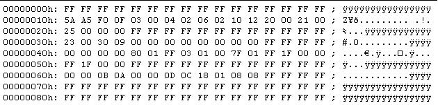
I can, however, tell you how the beginning and end of your image
"should" look. The start of the image should be similar to this
snapshot (from the G74SX, so yours may be slightly different).
The end of your reconstructed image should match the end of the
upgrade file you used. The last part of the upgrade file includes the
reset vectors etc. The overall size of your reconstructed image should
exactly match the size of your SPI device. For the G74SX, that equates
to 4MB = (2^22) = 4194304 bytes = 0x400000. I do not know what
size SPI flash is in the various G73 series models. I am hoping people
will report what they find, in their particular models, so we can start
a list of reconstruction offsets.
Good luck,
Sir RobinAttached Files:
-
-
Thanks for the SS
i hope it will be matching my Bios image =) -
So, maxslo, any update?
-
nope. ordered another clips in case the first one doesn't come, wich is fairly possible with chinapost. :s requested refund for the first ones.
i really hate this cheap mail for making me wait
-
ok just got the clips.
i only want to make sure everything else is ok before i start messing with BP. @evgasr2 my laptop behaves exactly like yours wihout graphic card. (from another thread you answered, i found link to youtube), is it just coincidence or could my GC be dead too :s ?
sorry for the mess, posting from phone -
i reproggramed the chip. still doing the same thing.
1. press power button
2. all blue leds go on including caps an num lck
3. CPU fan goes on for a sec then goes off
4. num and caps lck go off and keyboard backlight goes on for a sec then back off.
5. after a while both fans go on
6. nothing changes after that
i removed the GC and everything is the same except CPU fan is on all the time.
could the gpu be fried?
G73JH bios chip replacement
Discussion in 'ASUS Gaming Notebook Forum' started by maxslo, Jun 4, 2012.