
You will still be limited by the TDP of the MXM, I think it's 125W max for MXM 3.1
Also the BIOS can be an issue, but there are ways around that.
-
WhackingCheese, technically i cant take part; but you can count me in to support some kind of crowdfund.
Cheers -
Full height 16x PCI-E cards can use up to 75W (3.3V × 3A + 12V × 5.5A) from the connector. So the 100 and some watts shouldnt be a restriction for the socet. That's 1.1A per 12v rail and 3A over 2-4 3v3 rails, not really sure how many. but i'm suspecting that its: pin 8 side B, pin 9 Side A and pin 10 side A which would be 1A over each 3v3 rail skipping pin 10 side b as its auxiliary power. Besides wouldn't it be possible to use an external PSU to supply power to the PCI-E socket?
Last edited: Dec 9, 2014 -
Yes PCIe cards can pull 75 watts. Using 5x 12V 1.1A (66W) connectors and 3x 3.3v 1A(9.9W) connectors.
Anyway found this thread yesterday and tought it was interesting, im actually looking about going pcie to MXM. Im a sucker for small systems,
also would be awesome for a build im planning inside an amstrad CPC 464+.
After reading through a lot of the MXM spec sheet i started drawing it up on sketchup(only spent about an hour on it, WIP!), can't get pin counts to match ARRRRRRRRRGH
![[IMG]](images/storyImages/I1TpI7Ml.png)
Also its possible SOME systems could power the PCIe x16 card using only the MXM connector, it has 2x 3.3V 1A and 5x 5V 2.5A which could be regulated to 3.3V.
Since the PWR_SRC on the MXM can be between 7-20 is means that a system with a 12v PWR,SRC could directly power the x16 slot or one with >12v could be regulated
and used to provide the power.
That is just an option tough, the simplest way to do this is obviously to just power the x16 with an external PSU.
Apart from power considerations it seems like it should be straight forward wiring of the RX,TX,CLK,PRSNT from MXM to x16. -
Maybe, but it would have to be roughly in the power cost of the original laptop's GPU ( = really junky desktop GPU), because I know my laptop is pulling nealy 100% of what it's power supply can supply

I found this thread this afternoon and got all excited. Interesting luck that I rolled up just as the MXM documentation surfaced!
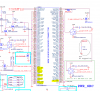
Anyway, I got so excited that I started making it in FreePCB. Which I have no experience with. But you gotta start somewhere!
Could anyone / everyone have a look and check that it looks right? It's essentially just the base board and the fingers. I've been working on it for almost five hours, so I don't think I can think well enough to match the PCI-e connections
My plan was to build a second PCI-e board and attach it with short ribbion (several standard 40-pin IDE) cables. Does anyone who knows something about electronics think this is a bad idea?
Other plan: match a cheap PCI-e riser, but I haven't looked at all into this option yet.
My FreePCB drawing: https://dl.dropboxusercontent.com/u/27091889/MXM/MXM_PCI-e.fpc
My FreePCB parts library: https://dl.dropboxusercontent.com/u/27091889/MXM/MXM.fpl
FreePCB Homepage (Windows only. Sorry ):
FreePCB: freeware PCB layout software
Gerber Files: https://dl.dropboxusercontent.com/u/27091889/MXM/MXM_PCI-e.zip
Online Gerber Viewer (Just feed it the .zip!): Online Gerber Viewer -
Awesome, great seeing new people get on board!
I'm almost done with all my exams, just the next Monday left and I'll be able to work on this for around 3 weeks. -
Pff. Exams. Passing classes. Pff.
Best of luck!
I've been working on a MXM pin to PCI-e pin spreadsheet. Could someone have a look and see if they agree?
https://dl.dropboxusercontent.com/u/27091889/MXM/MXM-PCIe Pins.ods
The one really big assumption I've made is that PEX_(RX/TX)x# is the positive side, and PEX_(RX/TX)x is the negative side.
For the PCI-e pinouts, I'm using that on the English Wikipedia page
https://en.wikipedia.org/wiki/PCI_Express
The other big remaining questions have I correctly matched the TX/RX pins? The TX/RX perspective in the MXM documentation is from the point of view of the card. So is the Wikipedia page. This means connecting TX to TX and RX to RX. Is this whole paragraph correct? -
the wire used in PCI-e risers is just ribbon cable like IDE, so it should be fine.
I would also think that the PEX with the # is positive and without is negative.
The Wikipedia page of the PCI-e slot is as if you are looking down onto a PCI slot, alternatively if you take the pins of the side of a card that has the fans that is side B and the backside of the card is side A
Pretty sure this is right, only wrote up to PCI-e x4. https://drive.google.com/file/d/0B48eIIer4qevN3VzQXhlMTBkN2s/view?usp=sharingLast edited: Dec 12, 2014 -
Okay. 11 hours later, I now have schematics through x4
All the links are the same. They will actually keep updating as I work on them
MXM board: https://dl.dropboxusercontent.com/u/27091889/MXM/MXM_PCI-e.fpc
PCI-e board: https://dl.dropboxusercontent.com/u/27091889/MXM/PCIe_Base.fpc
Two FreePCB libraries:
https://dl.dropboxusercontent.com/u/27091889/MXM/MXM.fpl
https://dl.dropboxusercontent.com/u/27091889/MXM/PCI-e.fpl
Pin-matchings: https://dl.dropboxusercontent.com/u/27091889/MXM/MXM-PCIe Pins.ods
Parts list (very incomplete): https://dl.dropboxusercontent.com/u/27091889/MXM/Parts List.doc
Zip of Gerber files for the MXM board: https://dl.dropboxusercontent.com/u/27091889/MXM/MXM.zip
Zip of Gerber files for the PCI board: https://dl.dropboxusercontent.com/u/27091889/MXM/PCI.zip
The big question is, is there someone who would be able to test this when it's finished? I can, but not until mid April. I usually live in the US, but I am currently living awhile in Germany (meaning if something goes wrong it will be a huge problem) -
Just something to keep in mind is that every laptop model might need a different MXM card to route the signals outside of the chassis. You might want to post your laptop model if you're working on a card for a specific one.
-
I'm working off the MXM 3 documentation which you posted on the 7th of December ~ Ideally, all laptops with an MXM port will be using these wirings exactly but the world of MXM seems to be far from ideal
If things go according to plan, I would use this with my MSI GT-683R, which I know can take Alienware mGPUs as upgrades (although the heatsink has to be modified, which seems to be against the standard!)
Other than that tidbit, I don't know anything specific about my laptop. But you're right, that even if this adapter works in some cases, it may not work in all.
(Conveniently, my donor laptop has a dead display, so I'm not at all interested in routing out the display pins. That's one variable off the table )
-
And uh, looking your boards so far i have to say that you do not need the 4 holes in the middle of the PCB, they are used to mount the heatsink on to the GPU die, in this case its not needed. All that's really needed are the two mounting holes on the top of the MXM card.
-
I considered leaving them out, but I decided to leave them in for three reasons:
1. They're not in the way (Or, rather, I worked around the one which was)
2. You never know when mounting holes could come in handy. Say someone wants to mount their normal GPU below this eGPU. I'm not going to say it will work, but who am I to stop their creativity with my laziness?
3. The MXM "standard" is incredibly fractured. I thought it would be a nice touch to make our board MXM compliant (Of course, someone will have to hook up the various display connections to make us fully compliant)
-
This is great and potentially the best solution to computer gaming, if you can manage to keep ahead of Thunderbolt in bandwidth and find away to efficiently power the external card from an external source this will be a real achievement. I hope you succeed, even though I will have no use for it myself, since it will truly be a victory of consumers over corporations.
-
Thunderbolt is only has 2 lanes of PCI-Express 2.0, this has 16 lanes. MXM was never intended for upgrades like Thunderbolt was. It was made so that laptop manufacturers would only need to design one laptop model for every GPU launch instead of having to make a special laptop model for every GPU. Fx. 1 for 980m, 970m, 960m and not 1 for 980m, 1 for 970.... It was never intended for future upgrades, it was designed by nVidia, designed to save time and have their products out faster which is why there are compatibility issues in certain laptops with never gpus.
-
Alrighty! Exams over, now i have a couple of weeks to work on this before school starts again. I have already made a library file for Eagle if anyone is interested in it. https://mega.co.nz/#!z0oHjDxS!THAQeRuU4a2mYdEiqK_xF60XLjDvX_3HfzQlH_qNla4
We cant have a card that needs to be removed every time that you want to disconnect the GPU from the laptop and go on the road since the connector is very fragile and it's durability is rated at 30 cycles. So i thought of putting a PCI-Express connector onto the MXM card to allow easy connecting/disconnecting of the GPU from the laptop. But i noticed that the PCI-E connector might only fit diagonally onto a type A card, if at all, which should be ok. So i think that my first prototype will have a diagonally positioned PCI-E connector. Tomorrow i will start working on a schematic for the MXM board.
If anyone could figure out how to supply sufficient power to a PCI-E socket without overpowering it, it would help out a lot. -
Since any GPU worth putting on a PCI-e x16 bus needs external power, I put a standard ATX Motherboard connector on my board to power it (since this is the job it's designed to do). This might be a little tricky for what you have in mind, since the connector is rather large. Maybe you could get a connector that runs a little way off the board and only has the three necessary (GND, 3V3, and 12V, as well as connecting GND to PWR_ON) connected? I haven't seen such a thing, but I would expect it to exist.
Mind you, I don't have any experience with these things. Motherboards are complicated. It's possible there should be electronics between the PSU and the PCI.
I hope you're successful!
-Sompom -
https://www.pcisig.com/developers/m...c_id=6d37ec2f8543fc1f9d8ace6264d08b469f57e5f1
Found these board design guidelines for PCI Express, It might come in handy! -
Depends what you guys want to use to power it, i would recommend a molex or sata connector from a regular ATX/SFX PSU , preferably sata as it has a 3.3v line and a 12v.
Molex would require you to either split the 12V and regulate it on 1 side down to 3.3v or use the 5v and regulate that down. Not that its a problem but most available Voltage regulators only provide 1A at its output meaning you would need 3 in squence, or 3 seperate lines(either is fine) to provide the 3x 3.3v pins.
Sata could go directly to PCI-e slot.
If you are using a ATX PSU you dont need to worry about overpowering the slot as the card with only draw what it needs, if the card needs 12V 10A, it will draw that so having a 12V 20A psu plugged into it wont effect it.
Though i assume this is the same for any 12V supply like a 12v AC/DC adapter, I'm currently powering my Radeon 7850 with a Xbox 360 brick(12V 16.5A).
So no extra electronics should be needed, apart from a few 3.3v regulators, if you decide to go that route. -
Well, its best to make this as simple as we possibly can, so sata power is probably the way to go.
The pci-e socket fits onto the MXM connector, barely but it fits! But i cant find how high the actual slot is, tomorrow i will design the mxm card and post it here for everyone to look at if i find the height of the damn PCI-Express socket. If someone could just go and measure the how high it is it would be much appreciated. -
PCI-e slot is 11.25mm in height
-
If you're planning to use the same PCI-e socket as I speced, the height is in the customer drawing, and is 11.25 mm (maximum). However, the part I have speced may give you trouble, because it specifically requires the PCB to be 2.36mm, while the fingers on the MXM board need a 1.20mm PCB. I suspect the PCI requirement is only so that the locking pegs fit correctly (which is not a huge deal, especially for a prototype), but this is something to keep in mind!
-
What about the CLKREQ# (Side B pin 12) and PERST# (Side A pin 11) are they required? Just asking because i cant find anything matching on the mxm module. Could PEX_STD_SW# be one of them? It starts of with PEX which is the pcie group, just wondering.
Last edited: Dec 17, 2014 -
I put that one to PEX_CLK_REQ# (MXM pin 154)
-
Gah, it was right there. PEX_CLK_REQ# and PEX_RST# are 154 and 152. :c i guess i need glasses
. Thanks man!
Sompom likes this. -
I have some concerns about the PWR_GOOD pin, In desktops PWR_OK is sometimes referred to as PWR_GOOD and PWR_OK is a signal sent by the PSU to the motherboard that is only sent when the PSU voltages have stabilised. The system is not allowed to start unless receiving a normal PWR_GOOD signal (a 100-900ms delay is usually considered normal) if the signal drops while the PC is on the CPU goes into reset mode and I guess that it tries to reset but it can't turn back on unless given a stable PWR_OK signal. I have no idea why it would be on an MXM connector but it's function is probably similar but instead of indicating a stable PSU it indicates stable outputs from the GPS? But I have read the MXM electromechanical spec so I at least know that it's also required for the mxm module to function correctly.
"no voltage shall be applied to any MXM module signal pin (except power pins and open drain
signals specified in Table 3.12) until PWR_GOOD is asserted."
"All output signals from the MXM module are undefined when PWR_GOOD is deasserted or
undefined. The system is reccomended to gate critical signals using an appropriate qualifier."
Edit 1:"Power sequencing sideband. The module will assert
this signal when all its internal power regulators are
within the required tolerance. 10KΩ pull-up required
on the system board if the feature is used." it indicates that the modules power regulators are worn the required tolerance.
We will have to find a way to fake the pwr_good signal.
Edit 2: PWR_GOOD is an OD (Open Drain) input signal from the MXM card to the system. In the MXM specification i'm not sure if its referring to the input to the card or to the motherboard but im pretty sure that Output is from the card to the module and Input is from the system to the MXM Module
Open Drain Inputs
Symbol / Parameter / Min / Max / Units
VIL / Input Low Voltage / -0.5 / 0.8 / V
VIH / Input High Voltage / 2.0 / V3V3+0.5 / V
Open Drain Outputs
Symbol / Parameter / Condition / Max / Units
VOL / Output Low Voltage / Iout= 8 mA / 0.3 / V
Isink / Sink Current / / 8 / mALast edited: Dec 18, 2014 -
I agree with you that the documentation is from the point of view of the card, so since it says output, it means we should put 3.3V on this pin when we're ready to be switched on. However, since my PCI-e board is not using any of the power options from the MXM slot, I think this doesn't need to be worried about too much.
I see two options:
1. Permanently connect PWR_GOOD to either pin 278 or 280 (3.3V). This may result in bad things happening; I don't really know how the PCI-e card is controlling its switching-on... According to Wikipedia, in the case of a standard desktop power supply, the PWR_GOOD is used by the processor, so possibly the processor tells the PCI-e card to turn on?
(That being the case, we should send the ATX Power Supply's PWR_GOOD to the MXM PWR_GOOD signal. But the ATX Supply is 5V! And this messes up people who want to use some kind of other power)
(The flipside of that thought is that the PE4H doesn't send any signal, because mPCI-e doesn't have a specification to send a signal. I think the only risk of having too-low voltage for a very short time is that the device won't function properly, which is somewhat unimportant since we're in the very early stages of boot-up. It's probably also not crazy to assume that the GPU power supply will already be powered on before the laptop is powered on => power will already be stabalized => simply connecting to 3.3V will not cause any problems)
2. Put a jumper on the board, with the option to connect PWR_GOOD to 3.3V. See if it works, if not, jumper it. All the disadvantages as before, but the advantage that you may never have to find out (depending on whether the 10K pull-up resistor is using it, etc.)
As an unrelated point of interest, in the PE4H, the PCI-e 3.3V is powered from the laptop's mPCI-e slot, so that is probably also an option for getting 3.3V, if you want to use that.
Reminder: My experience with electronics comes from >120V DC electric cars, not from digital electronics!! -
I would assume connecting PWR_GOOD (MXM pin 6 to PCIe A11) would work without anything extra required.
PWR_GOOD may not even be required, it is down as optional in the MXM specs for the system.
Even if it is, all electronics should be taken care of by the GFX. All the TX,RX pins need an impedance of 90Ohms, but again i would presume all of this is taken care of by the Card. -
I wired PCIe A11 (PERST#) to MXM 156 (PEX_RST#). But I could be wrong x.x
Right; but it would be silly to build up a board then find that it's useless because we need to respond the the PWR_GOOD, which is why I have added a jumper to my board (to connect it to 3.3V, which may still not be right) -
If your system requires PWR_GOOD than "Assert this signal within 90ms after PWR_EN" (Found this in the MXM 3.0 compliance checklist v10, if you google it you can easily find it) and should be max 0.3V and 8mA since its an OD output? Also i'm not sure if its a continuous output from the card or a pulsating one? Although looking at the MXM spec it looks like it should be a continuous output to the system.
Edit 1: Also PEX_STD_SW# should be tied to ground for a standard desktop PCI-Express swing level and not connected for a low swing PCI-Express mode. Whatever that means, it should probably be connected to ground.Last edited: Dec 19, 2014 -
The standing question is what happens if you just drive that signal high, which should be a safe approach if you're never going to use the power supplied by the laptop. What happens if the laptop doesn't want that signal (since it's optional)? Most MXM cards are designed by the same people as designed the laptop, so driving it high could damage something. Most importantly, what happens if you just drive it high without looking for PWR_EN? Before PWR_EN is asserted? I suspect nothing, but again, I have two already damaged motherboards that I'm planning to test with (That I don't have access to until April).
Where did you find the reference to 0.3V and 8mA? Table 3.19 in the Electromechanical docs seems to have those numbers as the *low* requirements but doesn't have a recommendation for high voltage...
From the graphic, it looks like it should be a continuous output, and in the case of an ATX Power Supply, if that signal disappears, the CPU shuts down.
Swing level has to do with how much voltage the card is allowed to pull. PCI-e specifies two, low and high (or half and full).
Documents:
http://www.intel.com/content/dam/do...rface-pci-express-sata3-specification-v09.pdf (Page 22)
https://www.pcisig.com/developers/m...c_id=2573906997f0aa441d878b8f9fe6673424b7b856 (Page 14)
I suspect that it should be tied to ground... And the first document says that a PCIe device can implement only the higher voltage if it likes. But, presumably, the PCIe controller should respect a device asking to go to low-power. Gah! Too many unknowns!
Actually, though, I just stumbled across the answer to one unknown. According the the Mini-PCIe electromechanical specifications: "However, the 'p' and 'n' connections may be reversed to simplify PCB trace routing and minimize vias if needed. All PCI Express receivers incorporate automatic Lane polarity inversion..." -- In other words, we no longer need to worry about whether PEX_TXx# is the positive side or negative, since it will be swapped if needed. -
Since PWR_GOOD is an open drain output from the card and this is and this is a document about the electromechanical specification for the card i looked at Table 3.19, Open Drain Outputs. And that's where i found it listed as max output for the low voltage. But unfortunately, there's nothing about maximum voltage for OD outputs anywhere in this document. Although there are listings for OD inputs both for low and high voltage so maybe that would work for outputs, but it could also fry the motherboard so idk.
Excellent, one less thing to worry about ^-^. Yes we do need to minimize vias to prevent signal loss but we also need to minimise 90 degree angled traces and we should probably match PEX trace lengths. (found this in a PCI-E document a while ago)
I'm going to hook up 1 pin headers to the pins that could be necessary/might become problematic so that it would always be possible to wire up a signal to them if they end up causing trouble. It wouldn't hurt to do it like this, would it?.
Edit 1: in the MXM 3.0 Compliance checklist v10 it says that PRSNT_L# and PRSNT_R# are supposed to be tied to GND On the module.
And since i couldn't find it on google when i checked if its still there, here's a DL link : https://mega.co.nz/#!Ht4VlL6D!0hY64UDVzc8u7wFYWZvXeP7iCW4oslHvbdVqUwEzKAU
Edit 2: OD (open drain) is listed as 3.3v open drain signal in Table 3.4. This leaves me well confused....
Edit 3: Well now that i think about it we still need to know if pins marked with "#" are positive or negative for REX_REFCLK.Last edited: Dec 21, 2014 -
Well i'm back christmas got in the way, so much for the whole 3 weeks thing >.<. But anyway i have been looking for a solution or at least a clew on the whole PWR_GOOD problem and whilst i was looking for it i found a EUROCOM document for their P180HM which has an MXM 3.0 Slot and in the documentation i might have found an answer to one or more of the outstanding questions. (its a service manual)
Here's the document : https://mega.co.nz/#!a8RkwToK!Y4kQW9CauTVu6a855hMwV08hwlZMRgNBFzWPEYUOkKs
This whole document has pinouts for every connector in the P180HM, a Clevo barebone released a year before the EM series.
On Page 68 and 69 there are schematics for two MXM 3.0 Connectors, one for the master device and the other for the slave device. (in this instance the master device is the main GPU, (this is an SLI/ Crossfire capable notebook) and the slave device is the other GPU.)
On both of the schematics there are 3.3VS line connected to the PWR_GOOD with a 10K resistor on the system board?
I suspect that we could connect one of the 3.3V pins to PWR_GOOD right after the motherboard applies the PWR_EN signal and that would work, 1A shouldn't be a problem.
ALSO PCI-Express lanes with a "#" appear to be NEGATIVE and the ones without appear to be POSITIVE. This might mean that every signal in the PCI-Express group marked with a # is negative but i'm still not really sure.
Heres are some screenshots from the PDF :

I'm just about done making my schematics and creating my parts list, soon i will order my boards and parts but not until I'm pretty sure that nothing apart from the bios will stop it from working.
Edit 1: I found the same document for my laptop model, the P150EM Clevo barebone. My specific one was sold by XMG under the name "P502" but this documentation should apply to it since the retailers do not design the laptops. (At most they can only make custom bios as far as i know)
P150EM Service manual: https://mega.co.nz/#!L4oRTQxY!OkQT40sTjKEpUyrXtfDWdWS7qxKA-8K8Bu1UUxj5Kiw
This has exactly what i need. And yes, it does appear that PCI-Express lane pins marked with a # are negative and those without are positive, including the PCI-Express Clock. At least for my laptop, but i think that this information might be applicable to other laptops.
Edit 2: Also if anyone knows what the S stands for in 3.3VS and in 5Vs please tell me, i can't find anything on the web >:c.Last edited: Dec 26, 2014 -
Seems like you guys are making massive progress. haven't been able to do much over Christmas with gigs and things.
I presume when they say 5VS and 3.3VS they mean VSB or Vaux which is just standby power. Which is why if you look at page B-42 in the second document you linked, the 'S' voltages are just outside the regular power diagrams, so they still receive power when the main ones don't. Example: 5VS is in the same power curcuit as 5V but is outside the switch, Which i assume is a Wake - Sleep/hibernate/standby switch.
For connecting the PWR_GOOD i would use a regular 3.3v line as standby is not a concern, considering the PSU is always going to be ON while the card is in use anyway. -
I've got a question that is not exactly the topic of this thread but this seems to be the best place to ask (as you guys seem really knowledgeable about MXM): is it possible to wire a connector to one of the MXM display outputs? The schematics in my P177SM(-A) service manual list several DP output pins on the MXM socket. I am not sure if they're functional and what should I try to wire them to. Perhaps you guys can help.
This MXM to PCI-E x16 connector is a great idea though. I am really looking forward to seeing it in action, like some sort of higher level Optimus that allows up to switch between a fast and a very fast GPU. -
Is your goal to be able to attach more monitors to your laptop?
While it's possible that an MXM GPU has more available display outputs that aren't outside the laptop, getting at them would be very difficult. I'm not really up-to-date with modern NVidia / ATI limits, but aren't both limited to 4 displays? In that case, you already have everything you could get (HDMI, mini-DP, DP, and the laptop display)
In all likelyhood, what you're seeing in the service manual is the connection that actually runs from the GPU to the ports outside the laptop, but having not seen that actual manual, that's only a guess
-
My goal is to connect a display directly to the Nvidia GPU, bypassing Optimus. I like Optimus for those times I'm on battery, but the bugs and quirks of the iGPU makes it a real annoyance while gaming. I don't want to have 5 displays connected at the same time.
On the service manual (that can be found here, if you're interested), I saw that:
I highlighted the pins that look like what's needed for a DP connection. They all seem disconnected (going by the cross on the wire, perhaps that's not what it means), but I don't know what should I connect there and how should I connect it. I was hoping that someone with a DP port on a non-Optimus laptop would be able to give me an idea of the components I would need. -
Ah. Now I understand! Yes, technically, I think that should be possible, but it could be difficult, because you have to somehow get the physical wires in to make the physical connection. I don't really have a suggestion to help you there
I have also been mostly concerning myself with the PCI-e side of things, so I don't have much information about the display-connections, but have a look at the official documentation, which I have quoted below. I think page 39 is what you're looking for, but there is more information in there regarding the displays.
-
First of all, happy new year!
Second, I found the full official Electromechanical spec for PCI-Express! It was on the same site as the MXM spec, it might come in handy in designing the PCI-E board.
Link : https://mega.co.nz/#!mxwQ1ThZ!F8bi0-ZGwB_wNaV6F8IcN-cH7Li_ZYEtkC-UIlMTsJo -
Following thread. Would be nice to hook up a dGPU to my MXM slot on my R4 and just use it as a desktop completely with external monitor. I would be happy
-
Any news?
-
From my end, I'm still waiting to get home (April) so I can test the design... I haven't heard anything from WhackingCheese
-
I'm not sure I understand - you are creating an MXM to PCIe adapter / board in order to use MXM GPUs on a PCIe slot?
Do you happen to know of any MXM to PCIe adapter / board for reasonable price?
I'm not knowledgeable with PCBs and electrical stuff. Do you think it will require too much from me (let's say, average student) to master it enough in order to create such a board?
Anyway,
Many thanks again and I'm waiting to see how it goes -
Splashy,
What we are working on is an MXM to PCIe adapter in order to be able to connect a standard desktop GPU (or other PCIe device) to a laptop through the MXM slot... This is not available to buy; at least not on the open market.
The other way, to use an MXM card in a desktop PICe slot, is available for purchase, but is not what we're interested in! For instance: http://www.pcidv.com/en/products.asp?id=628 (NOTE: I would be leery about putting expensive hardware into that somewhat odd adapter and then plugging it into my expensive computer before I've at least tried it with cheap hardware!)
The current design is extremely simple... A PCIe slot, ATX power, and a few standard pin headers. Anyone who has done some basic soldering before should be able to put it together. However, the current design is untested, so may not work!splashy likes this. -
1. Yea, I thought it was the other way around, but thought maybe you have something up your sleeve
2. My youngest pc component is from 2007 lol
3. I saw this pcidv thing, but I can't even figure out how to get it in practice. Also so "zentrica" modules, but they want only batches of 10 cards
4. Do you know how could I get such a board?
Thanks about the design advice!Sompom likes this. -
I guess you weren't wrong
Like I said, this isn't really what I've been working on; I've never ordered something from them either... My best suggestion would be sending them an email, or Google Translating the "How to Order" page. They have links at the bottom of their website to Alibaba and eBay, so maybe try there as well.
I saw your other thread where someone suggested contacting Sager. I don't know if they will/are allowed to sell you this, but they have always been very helpful and friendly when I've emailed them, so just try it!
I'm looking at the link I sent you before, and it looks like it may not be what you want. I can't remember all the tricks, but I think that's the older version of MXM. If you're using a newer card, make sure to get MXM 3. The versions are described on Wikipedia: http://en.wikipedia.org/wiki/Mobile_PCI_Express_Module.
If you have any more questions along this topic that you think I can help with, send me a PM, as it's fairly off-topic for this post
-
Hi, guys, congrats for your enthusiasm! Hope that you will manage to get this adapter working, it's gonna be very usefull and I think that many people, including me, would be interested. But may I ask how exactly are you going to trace the video signal of the external GPU to the Laptop's LCD? Does the external GPU has to have LVDS or what? Or you are going to use it on external monitor?
I came across this thread while I was looking for mini PCIe(male) to MXM(female) adapter - unfortunately doesn't exist such an adapter. But I found mini PCIe to PCI Express x16: http://www.hwtools.net/Adapter/PE4C.html, which may be usefull for me to connect MXM GPU on the PCI Express x16 slot (basicly it's the opposite of what you're trying to do). My idea is to use an MXM graphics card (they all should have LVDS) and to redirect the signal to the LCD (instead of the integrated or discrete graphics' LVDS) thru the mini PCIe port, which I am not sure that is possible. But for example, Lenovo T500 uses somethink similar - they have models with both integrated and discrete graphics and you can choose BIOS setting to switch between them. But don't know how exactly they did it - is it just based on software, or there is some sort of chip that is capable to control dual LVDS signals. Your case looks easier as the MXM's LVDS is alredy directed to the LCD of the laptop. -
In theory, it is be possible to put an LVDS back into the laptop through the MXM adapter. In practice, since we don't even have a tested prototype, this is being skipped in favour of simplicity.
I don't know everything, but I'm fairly sure this is impossible. The way current (DIY) eGPUs which power the internal display are doing it is either with NVidia Optimus with an internal Intel GPU, or some software monitor cloning (still having the internal display run by the internal GPU). If there were a way to directly connect to the laptop display through the mPCI-e port, someone probably would have found it by now!
Additionally, the mPCI-e electromechanical specification doesn't have LVDS lanes.
I don't know about that laptop in particular, but the older solution of multiple GPUs was there was literally a switch which could connect the monitor (and other video outputs) to one GPU or the other (So, essentially a special chip, but very simple). Ideally, you would then power down whatever other GPU isn't connected, but that isn't actually required!
Since this isn't really on-topic for this post, send me a PM if you have any more questions about this! -
I have been following this thread for some time. One aspect I was wondering about, is how you are going to get around the white list on the mxm port? This locks the port so that only approved cards can be installed in the laptop/workstation. This varies with the make of the laptop.
-
I'm hoping that, since we're doing something the laptop makers never predicted and only using the PCI-e part of the MXM slot, it will just work. However, of course, there is a high chance that this will work on some models of laptop and not others... In all cases, one possible solution is a BIOS mod... But again, since this has never been done before, maybe even that won't work!
At the least, I'm fairly sure my test laptops don't have a whitelist on the MXM, so I *may* be able to get something going
Let's figure out how to convert internal MXM connector an external PCI-E x16 box
Discussion in 'e-GPU (External Graphics) Discussion' started by toshiki, Aug 9, 2009.


