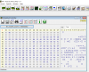
Value "C1" in register C6 means you are getting "full" power (unthrottled)
"40" in register C6 means you are being power limited by system throttle and NOS is disabled.
If the internal battery is disconnected, C6 will automatically be set to 40 and system power will be limited despite AC being connected. To avoid this, change EC register 31 to "09" (this will activate the battery circuit), and change EC register 42 to "64" (this will tell the system that the "missing" battery is at 100% charge, enabling NOS and full power).
This won't help with the master system power ID (register E3) though. Just useful for people who disconnect the battery for some reason and who don't want to throttle artificially.
-
-
@Falkentyne
One of my new failsafe vBios clips.
-
@seanwee, do you have some images of your shunt mod? I have some R005 surface-mount resistors on order, and know someone with a soldering iron, so hopefully I can do this within the next month or so.
-
So, the only way to discover if MSI is limiting my laptop to 230W or some other value is to shunt mod the GPU and put a power meter on the AC side of the charger, bench and see if goes above 230W..
Given that E3 is 52 isn't inspiring me much confidence that the increment by one still works.
And given that the GT75 topic is a bit dead I'm not sure if anyone with a 1080 or 2080 will ever post a screenshot of their EC registers Falkentyne likes this.
 -
Custom made, or bought?
Looks like resin printed "chassis" with a couple PCB's and pogo pins to put the pogos at the right location.
@seanwee And how did the BCLK overclocking experiment went, did you get the ICC profile working? -
Link please?
-
https://www.yanhuaacdp.com/wholesale/yanhua-mini-acdp-puncture-socket.html
https://www.yanhuaacdp.com/wholesale/yanhua-bmw-fem-bd-8pin-adapter.html
I got the idea from my car flashing tool sets.
Edit: To be clear. The first one is only for vbios size chips while the second one should be for bios size chips. I'll let you know when that one shows up.Last edited: Jul 23, 2020 -
Unfortunately I was too excited to test the performance I didn't take any pictures. And I don't want to ruin my best application of LM + carbonaut yet as the shunts are under the vrm heatpipe.
Nope, I'm on a trip atm so that's on hold. I did try the clip for a while before I left but unfortunately didn't have the right software to do the job.
@Krzyslaw managed to find a version that should work though.
Btw, I met ternauwies on YouTube and let him know that I managed to beat his timespy score.
He swiftly responded to say the least XD
https://www.3dmark.com/search?_ga=2...Name=NVIDIA GeForce RTX 2080 Max-Q&gpuCount=0
10.4k timespy graphics is pretty insane.
Still waiting for my CO2 fire extinguisher to arrive.Last edited: Jul 25, 2020Ionising_Radiation and Mr. Fox like this. -
Ah, snap. If you happen to reopen your notebook, do take some pictures if you can. Thanks for your insightful comments here, and your Time Spy score is incredible, by the way.
-
One of these days I am going to have to do the shunt mod on my TongFang turdbook and quit talking about it. I've got everything I need but lacking motivation because I know it is going to be too limited overall in multiple ways even with a huge improvement in GPU performance. However, I'm kind of getting the soldering itch again and need to solder something that good little boys are not supposed to be soldering. Since I moved back to desktops a couple of years ago I have become lazy and have lost interest in things that require taking my laptops apart because it is comparatively speaking a pain in the butt rather than a pleasure. The extreme convenience of a desktop with an open bench chassis has seriously spoiled me to the point of no return. However, the act of defiance and the sense of accomplishment derived from it is actually more stimulating that the higher benchmark scores. The joy that comes from giving a nasty finger salute to the makers of trash is very gratifying. Nice job.Last edited: Jul 25, 2020miloaisdua, Papusan and jc_denton like this.
-
I also got some plans about doing shunt mod on my MSI notebook.
I checked and there is few shunt resistors 0.005R, one 1206 case (probably for battery) and two 0612 (or something like this - reversed case, 4 pin terminal).
Due to specific case I do not have similar resistors to replace them, but maybe next month I will buy some to replace them.
I'm not a huge fan of using liquid metal/carbon on resistor - this is definitely troublesome and also make measure of those resistors much harder (resistance will vary due to how much LM you applied etc.).
Also some 4 pin terminal resistors due to it's nature and purpose should be bypassed by LM/wire/tin quite differently than regular, two terminal resistors.
Two terminals are just passing current trough (thicker/wider ones), another two are used for kelvin current sensing.
It look like this for 4 terminal resistors:
Two terminal resistors:
Anyway - for anything related to shunt mods itself I do really recommend replacing resistors directly than playing LM/etc. -
Might be a while but I'll ping you when I reopen it.
For me it's more of a habit. I like to absolutely maximise the performance of any piece of hardware I can get my hands on. It's the journey that matters, where I get to is just a bonus
On all nvidia implementations there are four terminals. I bridged the terminals on each side then bridged across the shunt resistors.
And yes, it's tricky to get just the right amount across the shunts where its enough to uncap the power limit but also not too much until it trips the built in protection.
I'm using solder btw, using LM to shunt mod in a laptop is a highway to having an expensive paperweight. Using thin copper wires is also not viable as it'll be either be too conductive or it'll be too thin to solder easily.
I did look into getting shunt resistors before I did the shunt mod but the minimum order quantity of 50 was hard to stomach. Its not too expensive but what am I going to do with 48 other shunt resistors?
If you want to go that route, measure the shunt resistors in your laptop first then look for 2/3 mohm resistors of the same size. You "can" use different sized ones but it'll be more troublesome. -
4 terminals are easier to use due to dedicated pins for kelvin sensing.
However desktop cards might still use regular, 2 terminal resistors (inch.1206/1210 case).
Bypassing 4 pin is easy to do, you need to short those 2 hi-current pins with a cooper trace or even tin (if those are close enough to do so) - much harder will be to calculate proper diameter and length of cooper wire to get that .0003R or something close to that value, but that still possible with calculator available online.
For me soldering is quite easy task, doing this for more than a decade
BTW I'm using MSI GE75 motherboard - it might be similar to your GS.
For resistors (depends when you live) I recommend to check Mouser, Farnell, Elfa or TME - assuming that your motherboard is similar then 0612 resistors will do the trick.
I picked those Vishay's due to low price and availability :
https://eu.mouser.com/Vishay/Passiv...0z7ymZ1yzkxaoZ1yocoqoZ1z0zls5&Ns=Resistance|0
I didn't check my whole motherboard, however I found two .0005R near my GPU so I assume those two are responsible for everything. -
I am going to try the 0.008 Ohm resistors that I used on the 2080 Ti on my 2060 BGA turd GPU. Tacking them in place with solder is super easy. Removing them is, too. I bought them at Digi-Key.
![[IMG]](images/storyImages/Omgt2Uz.jpg)
![[IMG]](images/storyImages/DbdmFZo.jpg) Papusan and mikolaj612 like this.
Papusan and mikolaj612 like this. -
Yep - those big 1206/1210 case is quite easy to de/solder.
However I do recommend to use only one resistor, adding more is not a bad idea but you need to calculate it properly 5mOhm + 8mOhm on top of it will give 3mOhm. -
Yes, it is better to avoid stacking and use the correct resistor if you know which one is needed. Stacking them can cause contact interference problems with other components in some cases. On the other hand, stacking makes removal and cleanup easier and more convenient if you ever need to RMA.
The end result is the same using either method as long as the resistance is correct.Papusan likes this. -
check with Mouser or Digi-Key. You can definitely buy in small quantity from Digi-Key as that is where I buy them in quantities of 5 or 10. The are also very cheap. The postage is usually more than the parts.Papusan likes this.
-
I forgot about one thing.
Stacking-up resistors will OFC change their overall resistance but also it will improve their tolerance.
If you stack up 2x 5mOhm 1% you will get 2.5mOhm with 0.5% tolerance.
This is a very good and also efficient way to get custom resistance and tight tolerance if necessary, 1% and even 0.5% resistors are quite common and then cheap enough to play with them.
Also I've got a good suggestion, instead of using LM to change resistance there was some kind of marker to regenerate/draw traces on PCB it should work well and also be more safe.
If you're going to use LM or similar method I do really recommend to use kapton tape and place on top of resistor.
Kaptop is quite heat resistant and also a good isolator.Papusan likes this. -
wtf are you saying, stacking 1% tolerance still result in 1% tolerance, worst case scenario, both 5mOhm are in reality 5.05 (so 1%), stacking two of them result to 5.05*5.05/(5.05+5.05) = 2.525mOhm which is still 2.5mOhm at 1% tolerance
Papusan likes this. -
Nope - stacking-up will result better tolerance overall excl. worst case scenario, anyway it still should be measured before applied.
However in this particular application it doesn't matter - I just mentioned it because sometimes it might be important, especially when you're looking for custom resistance that are unable to buy with tight tolerance (for example 0.1% or less).
I just read that in some book quite few years ago
-
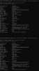
@prodj just upload his EC memory map, he has a GT75 8RG with a 1080, his E3 register has the value 31, while mine is 52, its a start, maybe.
Attached Files:
Falkentyne likes this. -
-
Hey Guys where do I look on the laptop mainboard to implement this on the GTX 1070 Mobile? -
The 1070 can be VBIOS modded, no need for shunt mods.
-
Yes I know. But I failed to modify the 1070bios. I gave up the bios modification, so I need that method.
-
Just look for 2 005 resistors, they will be near the GPU VRMs, hard to miss.
-
Thanks for answer.
-
i got mine from RS Electronics. You can buy quantity of 5. https://my.rs-online.com/web/c/pass...6,4292333469,4294884244,4292085623,4293458842
i originally shunted mine with thin copper wires which worked (software thinks power draw = ~30W when its really doing >100W). I later switched to 10 mohm resistors but i guess i botched the job somehow as i expected combined resistance of ~3.33 mohm with my 5+10 in parallel but in software it thinks i'm pulling 3.9W but since it worked without going in to limp mode i left it. main motivation was to be able to have known resistance so i can calculate the 'real' consumption from the software readout but i found it really difficult to stack the resistors and instead did this frankenstein job:
wire ---------
5mohm [] [] 10mohm
wire --------- -
Hey guys, is it still impossible to flash a modified bios using NVflash?
No one has ever bypassed Bios Cert 2.0 Verification, even though it's been a very long time since Pascal's release.
If someone invented a version that could bypass this, we don't have to buy hardware programmers anymore, and we don't have to worry about facing a black screen.
I used CH341a to touch the Rom chips but failed and faced a black screen, and in return, the laptop left me for more than a month.
The Gigabyte service center in my country failed to restore my laptop's 1070 vbios and now my laptop has been transferred to its headquarters in Taiwan.
But if even they fail, I will spend a lot of money to replace the main board.
Due to this trauma, I decided not to use a programmer to touch Rom chips anymore and now I decided to find a way to bypass the Bios Cert 2.0 Verification required by NVflash. -
Do it!
Does your eluktronics laptop have eluktroboost? curious to know if they already swapped the 0.005 resistors to something else. -
Why didn't you backup and then just flash back your VBIOS backup?
Doubt you will be able to ever flash a modded VBIOS, because you are going via the PCIe interface to the GPU core, and using the GPU core as your SPI interface, the GPU core, and thus the Nvidia drivers KNOW that you are trying to flash the VBIOS, if they dont recognize the checksum of the file, they dont let you flash.
Much easier to just follow proper procedure and use a hardware programmer, and make sure that your SOIC clip is making good contact than it is to write software that will circumvent Nvidia checks. -
I would love some high res photos of those laptop motherboards to take a peek, I would like to understand how do they do it, I guess that its a MOSFET that puts/removes an extra resistor into the current sense circuitry so the GPU core reads a lower current, and thus lower wattage.
-
You said "if they dont recognize the checksum of the file, they dont let you flash." Does that mean that the reason why the Bios Cert 2.0 Verification error occurs is because NVflash compares the checksum of the existing BIOS and the modified BIOS, and they are different? Do you happen to know how to exactly match the checksum of the original and modified bios? I found that the CRC32 of the original and the modified bios were different.
Attached Files:
-
-
OK, the through-hole resistor idea did not work. They are too large, so I ordered these: WSL12068L000FEA18
![[IMG]](images/storyImages/YcIlFns.jpg)
![[IMG]](images/storyImages/m2iM3uB.jpg)
@seanwee - here are some additional images that you asked for...
![[IMG]](images/storyImages/QJrXb3i.jpg)
![[IMG]](images/storyImages/7LnLVOe.jpg)
![[IMG]](images/storyImages/2hB4RzB.jpg)
![[IMG]](images/storyImages/kCFidKN.jpg)
-
Cant figure out much without manually probing the card unfortunately. Im not sure where the memory vrm ends and the core vrm begins, the lack of visible traces doesnt help either. Perhaps the backside of the mothrboard holds more clues. Could you take some more pictures?
The gpu power delivery uses a 6 phase controller and a 4 phase controller from Monolihic power so to give an educated guess its a 6 + 2 phase design. I cant find any information on the mosfets used however.
The two R030 resistors are part of the power/changing regulator circuit unfortunately and have nothing to do with GPU power. -
What do you want more photos of? I am not going to remove the motherboard and take off the aluminum foil liner on the back side of it. Too much work and I am not sure that if I remove that it is going to lay back down perfectly again. If you want photos of something on the exposed side let me know what you want and I will take photos when the resistors are here and I take it apart for soldering.
-
Just measure resistance between ground and every coil, core power phase will be near 0 ohms while memory power phase will be more than 10 ohms, but I'm thinking you have 8 core power phase (R12) and one memory power phase (2R2), or maybe it's a 7+1 or 6+2 shared on the "R12" power phase
edit : my final guess is this
Last edited: Jul 30, 2020Mr. Fox likes this. -
8 phase and 7 phase configurations are not possible based on the controllers they used unless they went with doublers but that's highly unlikely.
And the lone R2R phase for eluktroboost or for memory doesn't seem likely considering the small size of the mosfet beside it.Last edited: Jul 30, 2020 -
There is two driver, one can handle up to 6 phases while the other can use up to 4 phases, so it's 6+2 unless there is doublers, which is very unlikely.
The "2R2" is probably to feed m.2 slot power.
I don't know how eluktroboost works, does the card show 100+% TDP in load when eluktroboost is enable ? or it just stay below 100% TDP ?Last edited: Jul 30, 2020Mr. Fox likes this. -
Eluktroboost is activated on performance and benchmark mode if I'm not mistaken.
Assuming a 90w card, when running in balanced mode the tdp as shows 90w. When Eluktroboost is activated, the gpu recieves more power but the tdp shown is still 90w. So there is something feeding additional power to the gpu.
Something like this
Normal : 90w
Eluktroboost : 90w + 25w =115w
90w is fed through the monitored circuit and an additional 25w is fed though an unmonitored circuit.
There is another way to do this however. Since motherboards nowadays are all have many layers, a parallel circuit with say, 4 mhoms of resistance can be built into the motherboard, hidden from sight. Then when a software trigger is received, an IC switches from the 5 mohm circuit to the 4 mhom circuit. Basically a built in shunt mod.Mr. Fox likes this. -
Monitoring software never shows the power draw accurately. You can only tell based on what the entire system is using by what is being pulled from the wall outlet. Monitoring software will only report what the firmware "believes" to be true. It works that way for Eluktroboost as well as shunt mods. The same is true for desktop GPUs. My 2080 Ti will pull about 600W during a Time Spy run. The firmware power limit is 2000W. Software reports that it is pulling about 300-350W.
I wish I knew exactly what it consists of, but it is a proprietary secret that is closely guarded for obvious reasons. It involves a hardware mod of some sort based on what I have been told. But, whatever that is, it seems to work in connection with software. It gets activated by selecting the Turbo mode in the control center.
I have tried to spot something different looking on the motherboard and cannot. Maybe if I had an otherwise identical system without Eluktroboost sitting next to this one I could identify a difference somewhere.
It's not something I spend a lot of time thinking about. I do not rely on this laptop for entertainment and it doesn't have an overclockable CPU. So, it's all rather mundane in the grand scheme of things. It serves its purpose well enough. I use it primarily for work.
I am only looking at doing the shunt mod as an act of defiance and something that others might use as an example to eek a few more FPS out of their otherwise anemic laptop GPU. I do derive pleasure from both of those things. Plus, I haven't soldered anything for a while and I need the practice to avoid getting rusty.Last edited: Jul 30, 2020 -
They might be altering ILIM on GPU via software side.
Just like I did for my CPU while playing with BIOS settings. -
Hi@all,
i need your advice regarding TDP Tweaker usage.
my Card Hits 130w (Max TDP) then it clocks down. I thought i meight Reise the TDP to 140w to Prevent down Clocking. Temps are good (Max 78c.)
So what Values do i Need to change to bump up the Max tdp from 130w to 140w ?
What is the Black Screen issue ?
I did had one with a MSI VBios i Could only Boot into Safe Mode After driver install. Is this the Black Screen issue that the new Version of TDP tweaker is fixing ?
Is read there is a Option in tdp Tweaker to prevent throtle. Does anybody used that Option ?
Thank you all.JRE84 likes this. -
Hi. I am sure someone would be glad to provide some suggestions. Can you please identify your system (the make, model and specs). How much is it clocking down in MHz? Pascal and Turing "thermal throttle" starting at 45-50°C (which can be idle temps for many systems) and GPU core clocks continue to progressively fall as the GPU temperatures increase even though the temperatures are nowhere near being problematic. It's just bad behavior by design, but normal.
Also, are you using the high-performance Windows power profile with the AC adapter connected when you observe this behavior? Is NVIDIA Control Panel set to Prefer Maximum Performance for the GPU power management mode? If the answer to any of those three questions is no, that could result in degraded performance. If the answer to all three is no, then you should expect performance to be poor. The "Optimal performance" power management mode in NVIDIA Control Panel should be label "poor" performance.JRE84 likes this. -
https://www.techpowerup.com/gpu-specs/geforce-rtx-2060-tu104.c3495
Hey guys, if change the vBios of RTX 2060 with TU104 chipset to RTX 2080 vbios using a ROM writer, can you reactivate the CUDA core that Nvidia has disabled? -
Obviously not. Nvidia isn't that stupid and physically fuses off parts of the die to make it a lower tier card.
The only thing you'll end up with is a bricked card. -
Okay, thanks for reply.
-
Is it possible use a software flash on Pascal mobile GPUs yet ?
-
nope.
-
Thank You for helping me @Mr. Fox,
I do have already
“Prefer Maximum Performance”
“Ultimate Performance” Profile aktiv.
i use the 780w Powersupply from Eurocom. It seems to be a Vbios issue.
Could you help me guiding me threw TDP Tweaker Settings to set 140w ?
Does the Experimental trothel Stop Feature in TDP tweaker Work ?
What is the Black Screen issue ?
I get a Black screen with a MSI Vbios after Driver install (it’s the Part where the screen goes Black and comes Back again after successfull install). With the MSI bios it don’t go back to Desktop it stays black.
Is the Mxm 3.0B able to deliver 140-150w ?
Please help me.
Thank youJRE84 likes this.
Mobile Pascal TDP Tweaker Update and Feedback Thread
Discussion in 'Gaming (Software and Graphics Cards)' started by Coolane, Jun 20, 2017.