I have, along with a whole slew of others, that your experience is no where near typical...............
Here we go again. look at the pics I have posted of a well established installation that was taken appart and documented in pictures.......................
-
-
the dis colouration is from tim a bit blueich in colour like when you heat metall up yes?
when i saw my lapped 980x i thought jesus i must have run hot during my oc sessions.
i got a new cpu and i did my modds on the heatzink getting about 5 to 10c cooler temps dont know if its the modds or the new cpu but i could see/feel when i removed the old cpu was that the springs on one side of the heatzink was a bit looser then the other side it was like a slope on the cpu with icd micro thiknes on one side and good pressure and thick on the other
i also have some pics from after the removal of the chims i can up load if intrested and i can also give a more into it what i did to the heatzink
ps the gpu's are still running at the same temps as my first post -
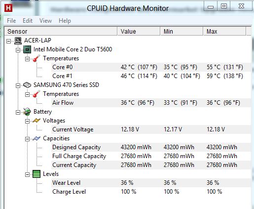
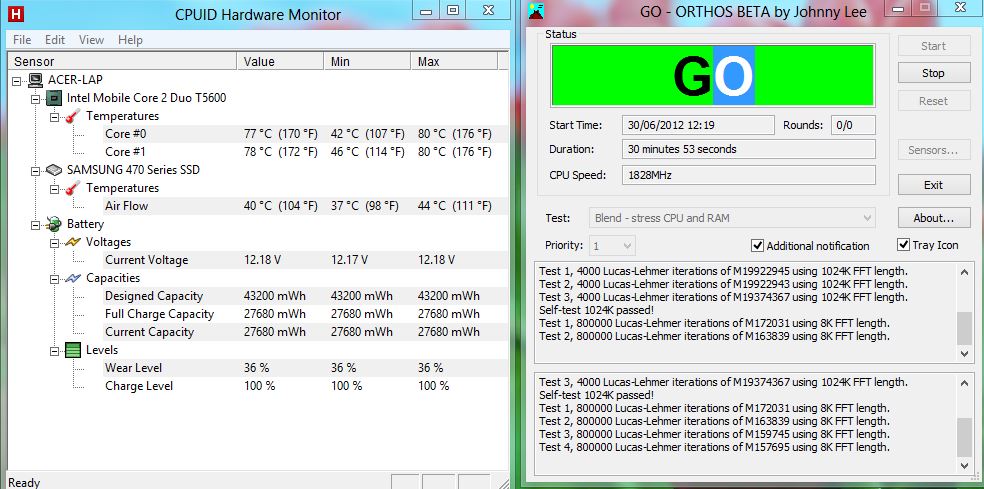
After 11 months of no activity. Here are my results (never reapplied the paste since my last post - because I didn't feel like it and because the tube is missing).
15m CPU Stress Test:
![[IMG]](images/storyImages/15mloadcpuambient281706.th.jpg)
15m GPU Stress Test:
![[IMG]](images/storyImages/15mloadgpuambient281706.th.jpg)
15m Idle after Stress Tests:
![[IMG]](images/storyImages/18midleambient28170612.jpg)
Seems that there has been an increase in temps. I would say that it is caused by the higher ambient temps (28 degrees C) than when I did my first tests. -
Sorry! been distracted with health issues as well as automating the processing. In any event I got back 2 of the 5 test kits from Too456 and yknyoy1 and preliminary pictures are posted below and they will be sent out for analysis on Monday and so should have the reports by the end of the week latest.
On the processor side so far including an earlier result in the thread 4 out of the 5 tested are marginal to nearly non existent on the contact and pressure. This kind of an issue will definitely impact the life of the compound as well thermal performance so we need more samples but the trend seems pretty strong and further sampling would confirm.
![[IMG]](images/storyImages/TEST8TOO456172630QMANDI5-520AND17720QM.png)
![[IMG]](images/storyImages/TEST9YKNYONG820QMANDNIVIDIAGT335M.png)
-
While researching the video we did on paste removal it became obvious that those that have a problem are using solvents improperly, that is to say that solvents have to be given time to work or in other words to re-liquefy the paste so it can be lifted off with no polishing effect or damage to the processor labelling.
I got the demonstration idea from TanWare - In the example we take a simulated copper IHS and some copper sheet that has a thin oxide coating only about 100 to 200 atoms (angstroms) thick or about 1-2 % of a micron. Now your lettering on the Processor ID is 100 to 200X thicker at around a micron or two.
In the Video we apply the compound and compress it to 95 lbs., 2X Intel's stock heat sink spec. on a digital scale.
We then remove the paste properly with acetone and demonstrate no damage whatsoever to the oxide coating.
The oxide coating is so thin and delicate that next to and through the unblemished, undamaged cleaned surface I am able to "polish" off the oxide with my bare finger in a few strokes.
We have always recommended acetone or equivalent solvent for IC Diamond removal and good shop practice is of course to let the solvent do it's work.
And keep in mind that with the exception of the Zinc oxide compounds thermal compounds are typically composed of metal oxides, the same oxides like aluminium oxide are what is used in sandpaper. Now diamond my be the hardest with a 10 on the MOHS hardness scale but it is only incrementally so as aluminium oxide come at 9 on the MOHs hardness scale. AS products as well as MX-4 and Shin Etsu all contain aluminium oxide and are in the liquid sandpaper class whereas materials like copper with an MOHS of 3 can be abraded without proper care or in other words not practising good shop practice. -
I hope everything turned out fine with the health issues. While I am hoping to keep my current install of ICD on the CPU I will have no choice but to redo the GPU. I purchased a later revision of the GPU fan and heatsink that is intended for my updated GPU.
As far as the CPU install I still have consistent temps from the last redo. As you have mentioned it is all about contact and consistent pressure across the die. Because of the thickness of ICD it is a bit more tolerant of an off kilter installation than a liquid material no TIM will work 100% without proper contact. -
Wow, that makes me thing that i haven't posted my temps for this month yet and it's time, one year worth of data:

-
Here are my readings after 3 months.
Room temps are 23 C degrees.Attached Files:
-
-
that's all great but it's not what happened to me. I always used arcticlean to remove TIM's and I never had any problem except with ICD and Coollaboratory Liquid Pro. The second corroded a copper heatsink (not aluminium). ICD ereased all the letters from the cpu surface. It could be a big issue because warranty was voided. In a previous job I had I must have reapplied TIM at least 200 times so I've a good number for comparation.
with a MOHS scale of 10 it just shows that it's not a good idea to use diamond based TIM's. -
The hardness of the materials used in thermal compounds are more than high enough to even scratch very hard heat treated steel (65~ hrc).
For things like copper, and aluminum it's like a knife going through butter.
I am fairly certain your issue with the printing coming off the CPU was a long time coming incident were the printing finally wore off.
I've done well over a hundred individual thermal jobs (different CPU's, I am not keeping count so could be more). On my previous AMD desktop ALONE the printing had worn off a couple of the letters after about 90 reapplications over a 1 1/2 year period when testing different application methods. -
Diamond is hardest but only incrementally so - aluminum oxide MOHS 9 - aluminum oxide you will find in arctic silver, MX4 and Shin Etsu and most others.
Many people do not understand the proper use of solvents and cleaners and lack patience so they squirt the cleaner on and start wiping immediately not letting it do it's work rather they turn it into a mechanical removal operation vs a solvent removal.
Good shop practice is to let the solvent re-liquefy the compound then wipe I recommend acetone as a better solvent.
I have a video almost complete on paste removal just have not had time to shoot the last scene we have been to busy automating some processes. I'll have to post it up on about four hundred forum threads to correct the misinformation when I get it done.
-------------------------------------
tijo & ellalan thanks for the updates
tijo thanks for the presentation - lots of work trying to interpolate peoples results much appreciated
-------------------------------------
I have the pressure and Contact test reports back and I will post them up tonight -
-
-
-
-
-
From Post 282
So out of the 5 CPU's Tested so far 4 are trending less than 50% contact which will greatly impact performance and long term reliability.
I would like to get a few more test results to firmly establish the trend but for most here it would seem significant improvement can be had by focusing improving contact as TanWare demonstrated with his mods. -
What are those things you use to test if there is good contact?
-
-
Yes I would like to do a test, it would be really interesting to see how good the contact is on my notebooks.
-
PM me your mailing address and I will send you a test kit. - How many notebooks?
I believe it is pretty much a foregone conclusion at this point that performance/reliability requires good contact/ pressure but I need enough samples for confirmation to template results so those that have multiple years with no change in temperature will likely have great C/P and those that only manage six months before temps start to rise will have something less in % of either contact or pressure. -
Hmm, now I'm not sure if my results would be useful though, because I repaste every couple of months, also my hardware changes too frequently.
-
Even so a library of contact images provides background data along with thermals is helpful
-
Updating results this weekend so if you get a chance p0lease post latest temps - do not forget to include ambient room temps
-
I did another cooling mod recently well after the ICD pasting so my numbers would be skewed. On another note I'll let you know as I may be doing a full tear down as I have a new better GPU fan to install. When ready I'll get some contact paper from you for the DB..................
http://forum.notebookreview.com/gateway-emachines/674081-another-cooling-mod.html -
I have no idea what happened to the post I made in April went but I have that and the new one I just did, The test I did in April had an ambient temperature of 25c and today's test was done at 27c. I also just finished doing the c/p test and I'll be mailing that off Monday morning. Surprisingly enough that I had the energy to do it considering I've been being worked to death over the last few months I haven't had the energy to do anything at all.
4/6/12:| 7/7/12:
-
Latest Give-away final results @ OCUK - For those who are interested in the Contact and Pressure side of things note the water coolers highlighted in red which trend to under performance pretty much with the exception of the Corsair coolers.
Poor C/P tend to show little difference between compounds and those who analyse results with out taking that into consideration are missing a key point about thermal compound testing i.e. that almost everything you need to know about thermal compound is in the Pressure and Contact, if you can not quantify the result (C/P)you can not qualify the result.
These results will not be an apples to apples comparison on temeratures as with a small die though you have less power on the laptops the watt density will be higher due to the smaller contact area
![[IMG]](images/storyImages/ocukfinaltable-2-1.png)
![[IMG]](images/storyImages/ocukfinaltable-2-2.png)
![[IMG]](images/storyImages/ocukfinaltable-2-3.png)
My argument on the water blocks is that they make too little contact with the IHS and in effect creating a heat dam
-
Recently retested my temps and they have stayed the same with no changes. Will update again in the future.
-
IC_ Diamond, you probably have a much larger database of recorded contact/pressure. This is going to be rather long... Sorry.
Unfortunately since all my "research" is personally funded, I do not splurge on very precise, nor very expensive equipment for good analysis on TIM applications, and performance. Hence I need your feedback.
You brought up a point that I wanted to ask.
1. Figure 1 shows optimal surface area contact. Which is what we should strive to achieve.
First I will explain my thinking on TIM application regarding utilizing the entire surface area of the contact zone:
In my testing due to various factors (uneven pressure, different angles, contact case flatness, etc) figure 1 has yet to be possible in a thin enough layer of TIM in my testing.
The two biggest issues seems to be: A) Not enough pressure. B) Pressure is uneven.
One could think, well I could just add additional pressure to fill the rest of the gaps, problem is once you release that pressure due to either A) Not enough pressure, or B) Pressure is uneven, the TIM after use ends up usually in the same spot it was before. (When heatsinks are removed, you can see a faint hint of where the TIM was thickest, and where it was thinnest)
What I found in practice is that:
Creating a perfectly even layer of TIM is darn near impossible, and creating a layer of TIM that reaches the entire surface of the contact case too is darn near impossible.
What usually ends up happening is you end up with a portion of the surface area with TIM, and a smaller portion without TIM. Essentially creating a heat dam albeit nothing close to figure (usually you end up using far more surface area)
I ran a small test about 1 1/2 years ago identical/similar 2 systems (same processors, motherboards, heatsinks, etc). 3 different applications.
1st Application was done optimally as possible. with a layer of TIM as thin as possible. Just to fill the gaps, not more. However didn't cover 100% of the surface. I believe it was about 80% of the surface area~.
2nd Application was done optimally as possible, adding just a tad bit more TIM and applying additional pressure for 1 minute.
3rd application, applying enough TIM to cover 96-98% (really more like 99.8%) of the surface area without requiring additional pressure.
(Method I used to figure out how much tim to use was to use Microscope slides of close size to the processor die, and apply thermal until it filled it completely- this is where budget restraints hold me down at times)
What I found was, the 1st application gave the best performance, while the 3rd application (being thicker than both 1st/2nd application) performed the worst. The 2nd application performed extremely close behind the 1st application however retesting 1st/2nd application really showed that the 1st application I am guessing due to less TIM used, while not loosing out on much if any surface area was still superior.
So finally my question is:
Does your data support the result? Or does it show otherwise.
The reason I ask is obvious due to the very small amount of systems tested I am hoping you have a larger database. -
Our Focus mostly has been on desktop systems and just starting to take a good look at the notebooks, bare die CPU's are pretty flat so most issues look to be mostly on the heat sink side as far as regularity of contact and pressure.
We always recommend to the high side on amount applied. I have taken applications of thermal compound with a synthetic die and a couple of glass slides compressed with binder clips(60lbs) then with a micrometer at measured intervals of time to compress or resolve to the final joint gap.
It takes about 5 min at room temp to compress to 95% of the bond line thickness(BLT) over night to 98-99% BLT - This is what people call curing the compound
What is happening here is the bond line is essentially your average particle size of the bulk loading of the paste and as the compound settles the excess is just squished out as it resolves down the average particle thickness for the final joint.
Basically you can never over apply you will still end up with best application that the mounting configuration can support. However if you under apply you will leave gaps that cause higher temperatures and shorten the life of the compound and of course the wasted time and compound in redoing the mount.
-
Right heatsinks seem to be pretty poor imho as far as machining (or casting more than likely) and rarely offer a optimal flat surface, and most of the times do not offer even pressure through the die.
You say you need a grain of rice or so for a 30mmx30mm I currently use less than that on laptops, for obvious surface area reasons.
Correct however I have yet to see an overapplication on a notebook, actually render the best results. I seriously think the issue is lack of pressure to actually squeeze all of the TIM out.
Does your data still say more TIM is better in notebooks?
That was my real question.
I know desktop heatsinks can vary, the pressure exerted on the ihs is quite astonishing at times, specially with some custom coolers.
I will grab a few test subjects tomorrow from work and check over application of TIM, although I suspect the result will be the same as before which was poor performance.
I would lap a heatsink to a very good tolerance but I am afraid I sold my granite surface plate block a while ago when I stopped polishing, which I have regretted ever since.
Anyways, I am heading out to a local electronics store. I need more TIM, and I also need more screw/small part organization boxes.
I don't think they got IC Diamond, but if they do I will pick up a couple syringes and report back here to do you some use as well.
Besides I wouldn't mind switching TIM's for work, it's been a LONG time since I did any thermal comparisons personally. -
Andrew!!!!!!
Awesome to see ya over here my friend. Has been a long time.
For anyone wondering about IC Diamond, I was originally in the very first tests that were being conducted with the, then new, IC Diamond 7 over at HardwareLogic. Awesome product. I am soooooooo looking forward to getting the new IC Diamond 24!!
None the less it is great to see ya Andrew! Been too long man. -
I like to overclock quite a bit, as such i lap/polish and 'balance' my heat-sinks (and the IHS if its terrible, which amds tend to be) so the pressure is as even as possible. Is there anybody else who has done this that has given results? I am curious how it performs under optimal (albeit pseudo unnatural) conditions.
-
Excellent point your making Mrzzz! It would be interesting to see some results from lapped heat sinks. Hopefully a fellow member chimes in and/or Andrew on this subject.
-
Definitely has an impact as again thermal compound is all about C/P -
On the OCUK giveaway one guy used the Contact and Pressure paper to optimize performance and independent of thermal compound he got a 7C overall performance improvement.
Mechanically getting the "perfect" mount will try the patience of the best of mechanic as the starting hardware (motherboard, HS, Mounting screws are all fairly loosely toleranced.
On our own synthetic test dies it is fairly easy to control C/P with 93% contact and calibrated spring mounts at 60 & 90 PSI My repeatability between tests is only a couple of 10th's of a degree and I usually run a few degrees better than the best real world lap job.
I use a belt sander to get the sink/IHS flat and then finalize with diamond stones, works pretty well but the edges are slightly rounded but not enough to make a real difference.
I have not looked at notebooks HS's but looks like we are headed that way as a part of the solution to the problem of high thermal loads.
I have had under consideration selling the C/P paper for some time to those that like to lap and could use it to jiggle into a better contact on their mounts it is rather a nifty tool even just using the raw images with no analysis -
I desperately need this C/P testing, as well as many Clevo P150EM/P170EM users. The GPU heatsinks for these models have been designed too cheaply, and the clips for the heatsink flex way too much for optimal pressure. I had my vendor apply an IC Diamond TIM application, and even this went down -10C after I modded my heatsink mount to add pressure in the correct location. But, I still have no idea whether or not optimal contact is being made or if enough TIM was used since I never took the heatsink off of the die yet, as I did not want to let air in since I have no IC Diamond at the moment to replace the application from the vendor. I'd greatly appreciate any assistance even if its just a referral to somewhere that might sell this paper.
Or I can try a thermal pad and see how it compresses over time possibly? Although I'd rather not cut thermal efficiency by 2/3 to test it, lol.
EDIT: Oh, I'm stupid. I just found that Fuji impression film link posted previously. lol. However, how am I to gauge what PSI I am going to need? I assume its one of the first 2 options. These heatstink clips are pretty weak so do you think 2-20 is a safe bet? -
I can send you some film and paste if you would do the CPU for me?
ultra low 28 to 90 psi even though the clip may be light but on a smaller area PSI will be higher -
Just re-pasted using much less compound than in the past.
Idle -
CPU:
45°C
44°C
38°C
46°C
GPU:
36°C
Load -
CPU:
85°C
88°C
84°C
85°C
GPU:
84°C
Results taken from my latest Vantage run:![[IMG]](images/storyImages/2jTbM.jpg)
Ambient is 23°C. -
Were these temperatures lower than before when you used more TIM?
-
![[IMG]](images/storyImages/OCUK%20Condensed%20Results.png)
Condensed version OCUK
For Comparison - I did not include all compounds as miscellaneous compounds tend to clutter the results and usually not noteworthy without a larger sampling.
AS 5 the most tested compound comprising about a quarter of our results runs about 2 C better than stock and the results here do not change much forum to forum. MX2 and MX3 nearly Identical in performance on this forum but does not match other forum results. MX4 half a degree better.
Shin Etsu did not test as well here as in other forums sample is not large so hard to tell (actually 17 end-user tests not 9 as posed above - typo on my part) The only thing about Shin Etsu could be perhaps it has a top recommended operating much less than most of the competitive compounds here (max 120C) so may not be as robust under heavy use found here.
Indigo Extreme was a good performer here and the liquid metal in general are very competitive when tested some liquid metals (LTM) on our synthetic test bed we found it equal to a solder joint about a .04-05 C improvement over ICD.
More later -
Very interesting results, thank you very much.
We may see a reason to switch to IC Diamond after I run some testing of my own. (Sorry got to remain skeptical).
Do you mind if I keep a copy of these results for business use (decision of buying TIM, not to publicize the material of course.) -
Updating the numbers and have a summary of results. Working on new format for the spreadsheet as is to cumbersome.
We also have 24 participants that have not updated their results who will get an email this weekend as a reminder.
Also many Thanks to those that have taken the time to update --much appreciated
![[IMG]](images/storyImages/Notebooksummaryjuly212012.png)
-
Im probably one of the 24 participants.

Just got myself a can of air so i can clean the notebook before gathering data.
Should be up shortly after im done at work.
Sent from my GT-I9300 using Tapatalk 2 -
Blaze Sempai C/P raw images - they are out for lab analysis and will post them when we get them back.
I think not too bad on the P8700
![[IMG]](images/storyImages/nOTEBOOKREVIEWcpbLAZESEMPAIJULY2012.png)
-
Older data is contained in this post: http://forum.notebookreview.com/har...veaway-reliability-survey-33.html#post8044549
So here is the updated results for my notebook.
Ambient temps are around the same as last time so around 25c ish but it should not matter much since i force the fan to a 100% on both results to get a fair reading.
Idle temps
![[IMG]](images/storyImages/ypP0nl.jpg)
Stressed temps
![[IMG]](images/storyImages/NQaA3l.jpg)
Did not collect GPU temps but i would say its probably near identical to last time i checked. -
I was surprised when I looked at the CPU one myself, one of the few times HP hasn't screwed that up
The GPU one is a bit lopsided though, that's held in place by only 2 screws diagonally across from each other , the CPU is held in by 4. -
Pressure May be a little light but I think more than compensated by the contact. They recently introduced a new C/P Paper and I am not used to reading the pressure on the fly with the changes I tend to overestimate what the lab analysis returns on it.
The bare dies are pretty flat and are some of the best C/P images we get. On the opposite side the heat sinks are pretty rough compared to an average OCing sink which is where most of the problems seem to be generated. I have noted with interest some of the mods done here to improve performance and as an indicator of need to solve a problem people are hacking into their systems.
Two point retention retention systems are not the greatest, a couple of 1000'ths in either direction and you get that %50 contact scenario you have on the GPU. I believe it is pretty much hit or miss as to whether you get a good contact HS in your purchased notebook. -
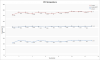
Ok, so i'm adding results for this month since i got the time even though it's not needed, also adding a graph for the CPU temp to show the trend so far. I'm thinking about comparing the trend in GPU average temps and CPU average temps since i think there might be some amount of heat transfer between the two despite the fact that they don't share the same heatsink.
Attached Files:
-
-
Good point, you can see that same thing in water blocks if they are colder than the motherboard - heat will follow the differential. Never thought water blocks should be tested on a mother board but rather on a synthetic system to filter the thermal noise but all things being equal the cooler block will perform better just the absolute block performance will be a little misty.
System cooling is a whole body kind of thing with a kind of feedback loop- reduce CPU temp and GPU temp goes down - Reduce GPU Temp and CPU Temp drops - Reduce both and other component temps drop HD,MB and so on for an overall lower thermal system balance.
This is where I differ with the rough equivalence in performance crowd A few degrees here and there go a long way in reducing system stress and decrease the odds of critical component failures. -
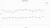
Well, here are the two trends. The error bars represent the standard deviation for the averages. It was either comparing the averages or comparing the max temps for the sensors available of each components. For now i'm gonna go with the average, but to be really thorough, i'd have to compare the trends for each temp sensors. Still i think it's safe to assume that there is a slight inverse trend between the GPU and CPU temps regardless of the error induced by the STDEV.
Here's the mobo for my G73, you can see the GPU on the left and the CPU on the right.

You can also see the G73JH poor GPU heatsink surface and yes, those are two different JH GPU heatsinks side by side: Imageshack - sany0054c.jpg. The surface for the CPU heatsink is much better, i think i have a pic somewhere, i can dig it up if it interests someone.
IC Diamond 24 Giveaway/ Reliability Survey
Discussion in 'Hardware Components and Aftermarket Upgrades' started by IC Diamond, Jun 8, 2011.


![[IMG]](http://imageshack.us/photo/my-images/35/15mloadcpuambient281706.jpg/)
![[IMG]](http://imageshack.us/photo/my-images/339/15mloadgpuambient281706.jpg/)
![[IMG]](http://imageshack.us/photo/my-images/641/18midleambient28170612.jpg/)


![[IMG]](images/storyImages/iNTELi7RAWIMAGE.png)
![[IMG]](images/storyImages/iNTELi7RAWIMAGESCANNED.png)
![[IMG]](images/storyImages/iNTELi7HISTOGRAM.png)
![[IMG]](images/storyImages/iNTELi73DIMAGE.png)
![[IMG]](images/storyImages/GT335Mrawimage.png)
![[IMG]](images/storyImages/GT335MHistogram.png)
![[IMG]](images/storyImages/GT335M3d.png)
![[IMG]](images/storyImages/Acerrawimage.png)
![[IMG]](images/storyImages/Acer83d.png)
![[IMG]](images/storyImages/hp8Raw.png)
![[IMG]](images/storyImages/hp83d.png)
![[IMG]](images/storyImages/Asus8.png)


![[IMG]](http://i.imgur.com/ypP0n.jpg)
![[IMG]](http://i.imgur.com/NQaA3.jpg)