
Lots of notebooks have the PM965 chipset, but they all have different PLLs.
The PLL is not part of the chipset, so the datasheet you found wont help you find the PLL.
You must find the datasheet (schematics) for your specific notebook. Because every notebook will have a different PLL.
Or just try using every PLL in setfsb.
Or take apart the notebook.
By the way, your GPU has a known fault, it will die if you dont keep the temp under 60C.
-
-
I finally managed to get a look a the PLL of the FL90, although under sad circumstances - the laptop is not booting anymore due to water damage and I wanted to check how severe the damage is.
However, here is a picture of the PLL (its the same that somebody already mentioned in this forum):
![[IMG]](images/storyImages/dscn0847x.th.jpg)
Which pins would I have to mod to set the fsb to 266 or stop TME. SetFSB does not work with that PLL. This is more of a theoretical question as I will not able to perfom this mod unless my FL90 comes back to life. -
@Daniel Hahn, download the datasheet here:
http://www.idt.com/index.cfm?partId=9LPRS365BKLFT
How to disable TME (basically the same as what I did):
From the datasheet you can see that the TME pin is pin4.
So you have to disconnect pin 4 from VDD and connect it to GND.
I have uploaded a pic here:
![[IMG]](images/storyImages/dscn0847x.jpg)
So I believe what I have marked pink is VDD.
Black is GND (check this with a DMM against the system chassis).
Blue points are connected to pin4 (check this with a DMM against pin4).
Red is pin 4.
If the above is right, then all you would have to do is move the resistor (marked "R1" in the pic) to the place marked "P2" in the pic.
That should disable TME. If I'm wrong about the GND point or those points I think are connected to pin4, don't do the mod. Make sure you check it with a DMM. -
How to set the FSB to 266mhz:
From the CPU Frequency Select Table (see datasheet):
FSLC__FSLB__FSLA
0-------0-----0----= 266mhz fsb (what you want)
0-------1-----0----= 200mhz fsb (what you have)
So to get a 266mhz fsb you need disconnect FSLB(pin 57) from VDD and connect it to GND.
Now I can't see what pin57 is connected to, use your DMM to find out.
You can see this pic for possibilities:
![[IMG]](images/storyImages/dscn0847x2.jpg)
It looks like pin57 either goes down a hole, or is connected to a resistor.
If it's connected to the resistor, just take the resistor off and use it to connect pin 57 to GND.
If it goes down the hole, you could cut the track with a blade and connect pin 57 to GND with a 10K resistor (get it from radioshack or rip it off an old junk radio, tv, pc, vcr anything broken and old...).
The TME mod would probably be easy, better off with it.
See the first post of this thread for links to other succesful pin mods, also read how I did my pin mod again because it's pretty much the same as yours. -
http://www.idt.com/products/getDoc.cfm?docID=18703881
my datasheet for ICS9LPRS365BGLF (same rectangular-shaped one pictured in above posts)
![[IMG]](images/storyImages/6ool0g.jpg)
My diagnosis:
![[IMG]](images/storyImages/2epiw45.jpg)
![[IMG]](images/storyImages/1676lad.jpg)
![[IMG]](images/storyImages/2hgfcx0.jpg)
My computer is a gateway e295c with viper-sr rev1 intel PM965 motherboard
When I select this PLL in setfsb, and try to move the top slider even just slightly, when i hit setfsb my computer crashes. I understand my PLL has TME enabled?
My cpu is a T7700 12 x 200mhz = 2.4ghz. If i tried 266mhz FSB via BSEL mod = 3192mhz, probably not obtainable or stable. I need incremental FSB changes, but don't know how to solder.... hehe. -
The BSEL mod doesn't work with this chipset (your multi will be locked to the lowest value). Also your ram is probably not stable enough to give you a 33%OC.
You have to do the PLL pin mod to disable TME as shown in the first post and this post:
http://forum.notebookreview.com/showpost.php?p=5795060&postcount=353 -
Do I have no options other than hard-mod soldering?
I"m not a computer person, and i just completely disassembled and reassembled this tablet pc just to find out which PLL chip i have... must have been 50 screws, and i'm surprised it still works (posting from it now).
When you say that it drops to the lowest multi, does that mean it attemps 8x at 266mhz... I have no problems with the ram since I can manually change the divider and timings to my liking. -
+1. BSEL pinmod applied to the CPU will lock your multipler to it's lowest setting, so can't overclock that way.
Your setfsb config register 9 has a value of 0x65, where TME_READBACK bit6=1. TME_READBACK=1 means "NO OVERCLOCKING". To change that bit to zero to allow software overclocking requires you to change the logic seen by the PLL on bootup as MH has indicated above.
So to overclock you have two options, both hardmods:
1. TME mod to allow setfsb software overclocking in 0.3Mhz increments up to point of instability [recommended]
2. hardset the PLL to 200/266/333Mz operation [not recommended as 200->266 is a BIG jump]. -
Yes, the CPU will be locked down to 8x 266mhz if you try the BSEL mod.
You could buy an extreme CPU, then you would also have to make sure your BIOS supports extreme CPUs (can your BIOS change the multi?).
When I did the PLL pin mod, I was a noob at that kind of stuff. All you have to do is buy a soldering iron with a really small tip and practise on some old junk motherboards. Also read about soldering on the net before messing with your notebook.
And take your time, it took me 2hrs to do the mod. The resistor is really really small. I almost lost it. Then I also made a mistake the first time and didn't make a good connection, the TME pin had no signal and the notebook didn't POST. So I had to take it apart and add some solder.
Also when I tried that mod on an older laptop, I put way too much solder and I couldn't get it off. So the notebook was FUBAR. -
The two of you are the fellas I was hoping would respond to my posts. So, it's a for sure that soldering must be done?
What about changing some of these hex values for the registers, does that accomplish anything?
TBH, I'm afraid of soldering on my motherboard. Also, Thank you for your valuable advice. -
I think you do have to solder. I guess you could try selecting the RTM*** plls in setfsb which sometimes have strange results for people with ICS PLLs.
I doubt it will work, but it only takes 1sec to try. -
Only final chance is to try the ICS9LPRS355 PLL. setfsb got around that TME-locked PLL by switching the main_src clock from PLL1 to PLL3, then programming PLL3. Below is the settings for a 189Mhz FSB operation using such a workaround. If you get a 189Mhz operation, then just need to alter byte 0C and 0D (13/14) to increase the FSB. There have been zero reported successes in using the ics9lprs355 PLL instead of ics9lprs365. Can also study registers changes by viewing the ics9lprs355 datasheet, here and here.
TME-locked ics9lprs355 running 189Mhz O/C FSB (setfsb switches main_src from PLL1 to PLL3)
![[IMG]](images/storyImages/ics9lprs355tme189mhz.png)
Other than that, your only chance of overclocking is the TME or PLL hardmod requiring soldering. Could take your system to a mobile phone repairer who'd have the finer soldering equipment to do it successfully. -
I'm willing to try any further software hacking, so I'll give these suggestions a go and report back soon... thanks!
-
No luck with any of the Realtek PLL's or the ICS9LPRS355. All i get is wacked out freezing & crashing while trying to adjust frequency. Thanks for your help & suggestions, I'll be considering this soldering thing now...
If i break it open and solder a 10k resistor onto that pin, or bend the 57+58 pins, is there some solder point i can access that will have an effect on the cpu's Vcore? -
You can pin mod the CPU to increase the voltage, guide:
http://forum.notebookreview.com/showthread.php?t=390696
(just scrol down to the socket P volt mod part).
You can look at this datasheet for the VID table (P23):
http://download.intel.com/design/mobile/datashts/31674505.pdf -
Developing a setfsb successor
NBR member Inteks has used the grub2-setfsb code to come up with a prelim setfsb successor in Windows. See
http://code.google.com/p/setfsb/wiki/Screenshot
http://code.google.com/p/setfsb/source/browse/
Not working as yet but coders welcome to join the project to help it along. AFAIK Abo has stopped development of setfsb based on his last website message so no new PLLs will be supported. This will keep the OC torch alive.
Inteks wrote 1810tray allowing overclocked-AC, undervolted-DC profiles but is now enhancing it for more generic notebook usage. setfsb being an important component. -
Hello everyone,
I loved reading this thread and it's so great to find really "hard-to-get" information here.Now I've obtained an Aspire 7740G and messed around with SetFSB.To PLLs were displaying Register Infos and correct FSB/PCIE/PCI clocks.
The two famous 355 and 365 chips.To my happiness the Register 09 showed 25 (means no TME if im right).But as soon as I change the FSB manually system freezes (no BSOD).I tried to crack open my lappy,but it wasnt possible for me to remove my keyboard.Anyway i made a screenie and i hope someone here might be able to tell me something based on that.Ah and another issue,I can change Register values without freezing but the changes wont show up on display or dont work.
Here is the screen
![[IMG]](images/storyImages/3651m.jpg)
Thank you for helping me solve this
Flow999 -
Yes it looks like you do have an ICS chip and TME is disabled.
Can you try changing byte 21 from 00 to 03. Then change any bit's in byte 13 and 14.
If that doesn't change the FSB, try this:
1. move the top slider a bit.
2. Click setfsb.
3. Take a photo of the registers just before the notebook restarts.
4. manually change each bit using your photo until you change the "bad" bit.
Make a note which bit is bad.
5. After the notebook restarts, change the bits manually again, this time leave the "bad" bit.
Hopefully it will work. -
thanks for your quick reply!!!
looking at my screenshot which byte 23 do you mean as values end with byte 15 (row 10 entry 05 is the last one)
when i change my fsb slider and click set fsb system hangs fully (register entries wont change)
anyhow I'll try to change some bits in register 13 and 14.
if there is hope to do a software oc that would be awesome")
-
Byte 23 is the last byte on the bottom row (current value "00").
If you click on it, you will see in the "offset" text box the following "15h (21)" which indicates that is byte 21.
Please change it from 00 to 03. then change any bit in byte 13 or 14. -
ah okay now i know.i did what you described with absolutely zero effect.I can do whatever changes i like and apply them without crashing my os,but the changes won't show up on setfsb nor will it produce any changes.(I changed almost every single register wil all possible values)
My guess is that,my ICS chip is a new type that isnt implemented yet.Could that be?SiSoft Sandra wouldnt tell me which exact clockgen chip i have only the standard "software programmable"(I unchecked "Ignore unknown PLL")
The best idea would be to crack my lappy open,but without a "service manual" i have no idea how to do that,without applying brute force.
Thanks for your ideas on that issue in advance
Flow999 -
Sounds like the PLL has a different byte for TME. And I think TME is enabled.
You're right, only option is to take it apart and find the PLL. Definatly needs a pinmod. -
I was afraid this would be the case.Thanks for telling me your thoughts.Any idea where I can obtain a service manual for detailes instructions on opening an Aspire 7740? I googled on that issue but only found a payed download site
-
Sorry I can't find the service manual, maybe you should start a thread about that in the acer sub-forum.
If you get it open, can you take a photo of the PLL, it would help. -
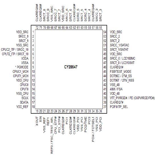
View attachment CY28547-datasheet.pdf hope this helps ,
is it really true setfsb is no longer being developed
-
Thanks for the datasheet.
I haven't emailed abo about setfsb in a long time, so I don't know for sure if he will still provide support. probably not. -
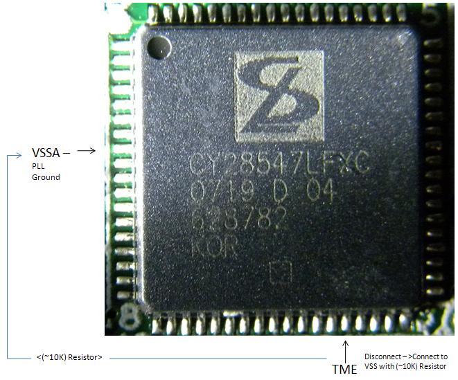
1. Pinmod disable TME mode then use setfsb software overclocking. Check status of config register 15, bit 7, (is byte 0F like shown on another PLL here) with setfsb's Diagnosis window. Try the various CYxxxx PLLs until one hopefully returns data there. If TME is enabled, then need to pinmod TME pin32 to GND to disable it. Then can try using one of the other supported setfsb CY28xxx PLLs, hoping for success since CY28547 isn't listed as supported. Advantage of setfsb overclock would be 1Mhz FSB overclock increments up to point of instability. Could ask Abo, the setfsb author) to see if he could add CY28547 support based on the datasheet link above.XPS M1730 X9000 overclocking the CY28547 PLL
Hikkoo, your XPS M1730 operates at 200Mhz FSB. The 2.8->3.4Ghz bios overclock simply changes multipliers from x14 to x17 as explained here. RAM operates at 333/667Mhz when running a 800Mhz FSB on the PM965 chipset.
If you want a higher overclock could try either:![[IMG]](images/storyImages/tmestrap.th.png)
![[IMG]](images/storyImages/cy28547tme.th.png)
![[IMG]](images/storyImages/cy28547fsb.th.png)
top: [CY28547] TME_check
mid: [CY28547] TME off
bot: [CY28547] FSB mod![[IMG]](images/storyImages/cy28551fsb.th.png)
[CY28551] pinmod FSB.
2. Pinmod the FSx pins directly to go from 200->266Mhz FSB. The CY28547 datasheet only tells the pins for up to 200Mhz operation, but the CY28554 shows pinout for 266Mhz, which *might* apply. That is, pull pin45 FSB to GND. If you wanted to try, would need to change your RAM's SPDtable to slow the timings for the 333/667Mhz entry, as booting up at 266Mhz FSB would mean it would be operating at the faster 444/889Mhz speed. You'd need to set the bios for the x14 CPU multipler. If it boots it would be x14*266=3.724Ghz.
See also kaltmonds X9000@266Mhz FSB overclock.Last edited by a moderator: May 7, 2015 -
Wow, interesting, That is the same PLL I have in the Inspiron 1720. Link is a pic of the PLL off my motherboard in my Inspiron 1720
-
Is this accurate? It's a diagram pic. Or do I need to rotate the side?
Attached Files:
-
-
The diagram you present is the correct way to disable TME. Before doing that, refer to an update in my previous post showing how to check using setfsb's Diagnosis window if TME is already disabled.
-
Ok thanks, I'll do that in a few hours, I'm not going to actually pin mod it, but rather, just curious and looking for an understanding of how it all fits into the larger picture.
-
My Laptop is a m5550 R3 i and it'S PLL should be ICS 9LPR310BGLF any one knows how to unlock it or is it supported in setFSB
Intel 945M Chipset with 667FSB and T7200 -
ICS9LPR310BGLF is on the list of available PLL's.
-
ok i was wrong, just downloaded it again and now it took
ICS9148BF-26 looks like i have another rev. of the Mainboard inside my laptop.
now i can set everything except the SetFSB slider that means there's something locked
![[IMG]](images/storyImages/m5550setfsb.jpg)
-
setfsb either can't enable the SMbus or can't access it for some other reason.
You should just pin mod the PLL to 200mhz. -
thanks for info Nando & MoralHazard
TRied all five CY........ on setfsb with no success
(would be really nice if Abo passed his "no how" to someone else, so they can get a million hits )
so looks like a HW pinmod, Main concern is Heat @ x14 266Mhz FSB because the 3 fans in me xps only come on continously (100% speed) when set in bios to x16 an x17. (so far no one's been able to control all 3 fans)
My question is , is it possible to HW pinmod from 200Mhz to 233Mhz FSB? then could set in bios to x16 233Mhz FSB(3728Mhz) which insures 3 fans on @ 100% speed continously -
Probably not. But it depends on that PLL you have. I haven't seen 233mhz before though.
In fact, looking at the datasheet you've linked to, it shows 100, 133, 166 and 200mhz. I dont know if 266 would even be possible for you. -
you just never know, worth a shot! and same for Method3 might not work either. First appling new thermal paste an ile take photos possible have a different PLL
EDIT: Do have PLL CY28547 in XPSM1730 .
Lol...didnt know the PLL was staring at me every time open Memory Cover but need to shine a light at PLL an set camera to "Digital Macro" or magnifying glass to read it.
size of PLL is 10mm x 10mm. -
+1. Yes, the PLL datasheet Hikkoo has linked has only up to 200Mhz, but another PLLs of the same family shows the FSLx pin logic to go to 266Mhz. See details here. The way to get a smaller increment would be to pinmod disable TME to allow the PLL to be software programmed. using setfsb/grub2-setfsb/rw-everything.
-
Awesome writeup. Will be trying this within the next week or so (hopefully today).
My specs are as follows:
Acer Aspire 5920g
t5250 (1.5) Merom Core CPU
8600M GT gpu
The PLL with the data sheet is 9LPRS365BGLF. Will most likely start with method 1 in much the same manner and go from there.
Attempts to use setFSB have just given me a bit of a head scratching; changing values within the main sliders and hitting 'Set FSB' force the sliders back to their original positions. Attempting to change settings in Customize, although stick after 'Set FSB', didn't appear to have any effect on the system (checked with rivaTuner, cpu-z, OCCT, and just maxing out all values expecting a BSOD, to no avail.)
As an added note, within the setFSB utility you can see the smBus read out under Diagnosis. Is this the same as described in method 0 for linux machines?
(ie: my read out:
40 00 08 95 D3 03 00 05 00 44 00 00 02 00 07 07 )
Can this be reliably used to check for the TME variable? -
TME_Readback is register 9, bit 6. In you case register 9=44h, bit 6=1. So TME is enabled on your PLL. To get ics9lprs365 working within setfsb would require the TME pin grounded via a 10k resistor. The TME pin on a rectangular PLL is pin 4, on the square PLL is pin 11.
-
Thanks for your reply! Hopefully it'll be noticed and thrown on the main post so people can check through setFSB on windows if tme is enabled.
Still a bit new to working with wires beyond *very* basic bread boarding. If I have access to a potentiometer, how would I go about finding the ground, and then testing a resistor to be 10k? Previous posts have shown to simply use the one already on the board... would I have to make sure this is 10k? I know well enough how to make sure it's connected, to the designated pin. Won't be tearing things open until I get access to a soldering iron, however.
*making a few notes here rather than bumping the thread:
acer5920g with a t5250 1.5 cpu
3dMark06: 3090 (1289, 1158, 1316)
Temps:
85c for the GPU on 15min of OCCT
70c for the CPU on 15min of OCCT -
Hi! I am new here, but I've been around reading some posts so not so new.
But I do need some help with pinmod, or if I don't need it. PLL is - SLG8SP510T
How would I go about doing this? My computer is an ifl90 and it is a pm965 chipset. -
The datasheet shows the SLG8SP510T is not software programmable. You could however do is a 200/800->266/1066Mhz FSB overclock by disconnecting FS_B pin57 from the rest of the circuit and routing it to a GND via a 10k resistor.
To bootup in 1066Mhz FSB, your RAM would need the 333Mhz SPDtable entry modified for 444Mhz operation as that is what it would be running now. If your bios can disable speedstep to hold the lowest multipler, it might be useful during your testing phase to see your CPU's tolerance to this overclock. -
Thanks Nando!
-
hi
i was wondering if i can do this mod on my dell studio 1535 (specs in sig)?
And just telling you im a total noob with inside a laptop stuff. Can this damage the laptop? and what do i need? do i need anything special? like something that i have to buy? -
You can completely destroy your laptop if this is done incorrectly.
Soldering components this small require more than just a 'cold-heat' gun from your local wal-mart, unfortunately. -
well i got a spare mobo fortunately for this laptop but with an onboard graphics. Is it hard to do this? do i just need the soldering gun or do i need anything more?
-
Before trying, can you take a photo of the PLL, and produce a dump of the PLL registers using setfsb->Diagnosis window? That way can can check:
i) Is software overclocking possible: check the TME_Readback flag to see if TME is enabled AND confirm if the PLL is on the setfsb list of supported PLLs. If so, could do a TME pinmod to enable software overclocking
ii) If can't do a software overclock, the could consider a PLL pinmod to alter the FSLx pins, eg: 200/800Mhz->266/1066Mhz FSB. Be prepared to flash the SPDTable of your RAM before trying as it would need 444Mhz RAM timings in the 333Mhz entry (since it would still think it is running 800Mhz FSB, where RAM runs the 333/667Mhz timings). Your T8100-2.1 CPU would be overclocked to 2.8Ghz which may also require higher voltage for success. See voltmod thread. -
Ill try to take the pic when i can. BUt first, wheres the pll?
and what do i do after going into diagnosis in fsb?
PLL Pinmod Overclocking Methods and Examples
Discussion in 'Hardware Components and Aftermarket Upgrades' started by moral hazard, Jun 24, 2009.

![[IMG]](http://img215.imageshack.us/i/dscn0847x.jpg/)


![[IMG]](http://img5.imageshack.us/i/tmestrap.png/)
![[IMG]](http://img203.imageshack.us/i/cy28547tme.png/)
![[IMG]](http://img708.imageshack.us/i/cy28547fsb.png/)
![[IMG]](http://img689.imageshack.us/i/cy28551fsb.png/)


![[IMG]](http://img171.imageshack.us/i/m5550setfsb.jpg/)


