Shin-Etsu has a good overview from all their pastes, all the bigger manufacturers with multiple thermal paste products should offer such an overview. In most cases we can't even get the viscosity number.
![[IMG]](images/storyImages/grease_ref_data152jq1.png)
![[IMG]](images/storyImages/grease_ref_data2pwkw4.png)
https://www.shinetsusilicones.com/thermal_grease.html
-
-
Shin-Etsu G751
78/85/81/81
Shin-Etsu X23-7783D
80/88/82/85
Arctic MX-5
80/92/84/87
Be Quiet DC1
76/85/80/82
SYY-157
75/83/79/80
Shin-Etsu G751 is a very thick paste, one of the most viscous I have ever tried and difficult to spread. It's not reaching the top stuff I have but it works. The higher rated Shin-Etsu X23-7783D is much worse, it's not as thick. -
Yup, basically you put a slightly more generous amount and then spread and thin it until it’s about half a millimeter thick. Makes spreading a heck of a lot easier.
-
Aliexpress
I think this is the highest rated traditional thermal paste in the market right now. Of course these ratings are not really meaningful, especially for a notebook. I have tested some low 3-5W/m-k rated pastes which were better than many of the 8-13W+ rated ones. -
I want to test this paste but would be at least 3 weeks shipping time and I think I'm done spending money. I don't know. How is this going to be better than TFX? And the viscosity rating isn't shown on the package.
-
I would like to try as well (if it's available in Germany or EU) but I do not think this paste is a top contender for a direct die chip because this paste is made from Halnziye . I've tried 3 pastes from Halnziye so far (HY-883, HY-A9, HY-P13) and all were not that great for me. I will try HY-810 soon because it was the best Halnziye here: https://www.how-fixit.com/best-thermal-paste-for-laptop/
Deepcool Z10 and EX750 started to appear in Europe, if all goes well I can try them out next week. I have big hopes because the lower rated Deepcool G40 performed really good. Another big hope for me is Akasa T5 Pro-Grade+, there are first listings in a few czech shops so it might be available in a few weeks. Very high viscosity and diamond based, basically every diamond based paste I have tried performed really good in my tests which makes me think this paste could perform really good. -
Tested Z10, EX750 and a few others today. It was so close I made two applications. It's not clear to me yet which Deepcool is the best but all of the Deepcool stuff is amazing for sure, SYY-157 isn't better. Interesting to note that the Z10 is by far the thickest/driest from all, yes it's thicker than SYY-157. It's like Thermalright TFX light. EX750 viscosity is more comparable to SYY-157 or Deepcool G40, its a lot easier to handle than Z10.
SYY-157
74/82/76/80
75/82/78/78
Deepcool G40
75/83/78/80
74/82/75/78
Deepcool Z10
74/83/76/80
74/82/76/80
Deepcool EX750
74/82/78/78
75/82/76/78
Foshan GD900
81/92/83/88
Akasa 5022
78/86/81/84Falkentyne and tilleroftheearth like this. -
Where did you buy Deepcool Z10 from?
-
From edigital.de, it's a hungary based shop. On ebay there is a US based Z10 seller if you are interested. Even though initial temps are similar, I wonder if the higher viscosity of Z10 has a longevity advantage.
Btw GD007 should work better than GD900 (both are from Foshan Electronic), GD007 looks much thicker here.
Just saying because GD900 is a popular paste but for a notebook it's not thick enough. Thermal Conductivity number is so meaningless for a notebook. I also made a mistake with the Zalman STC9, I should have buyed STC8 instead.
STC8 8.3 W/m·K 350 ~ 480 Pa.s
STC9 9.1 W/m·K 250 Pa.s
STC8 is thick paste unlike STC9. I really can't wait for the new Akasa T5 Pro-Grade+, super high viscosity and nano-diamond particles should work really good for my CPU.dmanti and Falkentyne like this. -
Please let me know when you find a seller where I can buy the T5 Pro Grade+ from in USA. I'd be happy to try it even though I'm just wasting more money

-
There are first entries in some european shops but I think we have to wait some more weeks.
-
I'm puzzled about Akasa 5022. I still have the application from yesterday on the chip and the temps are 2.5 degrees better compared to yesterday. I have never seen this before, this paste must have a big curing time. Ambient temp only -0.2 degrees down to yesterday, this can't be the reason. Tried several runs and simulated my usual test procedure (10min prime95, 2min cool down before shut down and 10 minute after the last prime95 run another 10 min Prime95 run), this is the result:
Akasa 5022 1 day later
76/83/79/81
It's "only" ~2 degrees down compared to Deepcool/SYY from yesterday at almost identical ambient temperature.tilleroftheearth likes this. -
Looks like it's staying on a few more days then!tilleroftheearth likes this.
-
So, something with drastically wrong with my TFX application. It worked great when I first put it on, but it's been a week and now that I tried running a benchmark or stress test, and two of the cores shoot up past 90-95 C and start thermal throttling immediately.
I'm not sure what to do now. Should I reapply TFX? This stuff is supposed to be thick I thought? Should I switch to IC Diamond? I might go for pea method because I know I can't screw that up. -
It's Core 2 that's spiking high with Core 4 right behind (i7-8850H ). Anyone know which part of the die that's in?
-
I repasted it, temps back to normal now. The paste was still pretty pliable and cleaned off easily. Looked like the left side of the CPU had the paste pushed off of it from when I tightened the heatsink. I tightened the heatsink a bit differently this time, but was still rushing. I tightened the first screw a bit, then 2, 3, 4, then went back and kept tightening them the full way so hopefully it doesn't get pushed off.
But that it reached this point where the cores would overheat about 1-2 weeks after running fine for a bit suggests some pump out, no? And this was TFX... Would applying too much paste make this more or less of a problem? -
What temps do you get initially? I haven't seen a drop off after 1-2 weeks when I did use TFX for a bit longer, the thing is every notebook can differ. I would say more paste is better, even with a big layer of TFX my (initial) Prime95 temps were always great and I doubt it hurts the longevity. -
This seems like a standard warped heatsink or mounting pressure problem. Provided of course, the heatsink is actually flat, and it was the mounting you did the first time (uneven) which caused problems, but all of that needs testing.
If you did have a convex / concave heatsink though (Flat but imbalanced is another problem), depending on how the heatsink is fastened, the only way to avoid this kind of problem, in order of desirability, is a washer/spring mod, and VERY minor flattening of the heatsink and CPU die (if possible) to try to remove as little as possible of the part of the heatsink that is not flat. It may be possible, under the least desirable sanding method, to flatten the CPU slightly if you had a small piece of glass, small enough to be able to wrap some 1000 grit sandpaper around it, but other than that you would have to work on the heatsink. This can work, but you want to do as little as possible--you don't want to reduce the z-height of the heatsink at all--you just want to reduce the convexity or concavity. In this case, the less sanding you can do, the better. The best way to determine if you have such a problem is with pressure paper testing.
If you have some sort of device or contraption that can measure actual flatness of a surface somehow (i know nothing about this), that might help even more. But if not, you would need to test the hard way, to determine what needs to be done. Perhaps you can consider sourcing some "Fuji Film Extreme Low Prescale" contact pressure paper (or Ultra Low). Innovation Cooling had them on ebay but they seem to be out of stock.
(Sensorprod.com which is fujifilm's US reseller, has offered free samples in the past, if you requested it on their website, but I do not know if they still do. I did get three samples from them before).
Maybe contact Innovation Cooling or on their main website and ask if they have more stock available somewhere (I believe they also make IC diamond thermal paste, as well as retail the Graphite Pads (from Panasonic Soft PGS+ series).
https://www.ebay.com/itm/264362353892
First try the washer/spring mod. If the screws are top mounted, with springs inside the screws, with a "C-clip" that sits between the spring and the bottom of the heatsink, you should remove the C-clips first, then mount a washer that will go on top of the heatsink, that will then help compress the spring (the spring will be above the washer). I don't have the specs of a washer you need, but it would be similar to the washers used for AMD Vega 64 and RX 5700 XT "pressure mod" video cards. This should help to create extra downwards pressure. You may have best results by a very minor sanding of the heatsink combined with a washer mod. Then as before, carefully screw in with the alternating partial turn "X" pattern.
I do not know if your heatsink could even use such a mod. The MSI GT series laptops worked with such mods (after you remove the C-clip), and some Clevo DTR models had similar mods done in the Clevo section.Papusan, dmanti and Rooter1234 like this. -
It should have been mid-80s like it was on all other cores except those two, which were shooting up into the 90s.
I put on a thicker layer of paste, including to cover the left side, so I guess we'll see if it happens again.
EDIT: It was cores 0 and 2 which were hotter. After the repaste, they're still about 3 C hotter than the next core and 5-6 C hotter than the coolest two cores.
@Falkentyne: I'm worried about using the washer/spring mod, is it possible to have too much pressure? Wouldn't that squeeze out more paste from inbetween the two contact surfaces?Last edited: Aug 6, 2021Rooter1234 and Falkentyne like this. -
Better pressure is always a good thing as long as its perfectly balanced and not concentrated on one spot unevenly. Obviously too much pressure is dangerous as you can crack dies or bend PCB's, and I am not qualified to tell you what an ideal PSI value is, but I'm guessing 40 PSI is a good value on direct die. Yes of course the paste will be squished out. But if the pressure is perfectly balanced,flat and even (e.g. perfectly flat heatsink and cores) this is exactly what you want. The problem is getting there. A washer mod helps keep the pressure more constant as it helps counter loss of pressure from thermal expansion/contraction and paste shifting around unevenly due to imbalance, provided you balanced it perfectly initially.Papusan likes this.
-
For some reason, Cores 0 and 2 are the hottest cores at max load (about 5 C hotter than next two and 10 C hotter than coolest two out of a total six cores), and also consistently the coolest at idle by 1-2 C.
Temps are stable for now on those two cores within tolerable range (85-87 C peak under non-AVX stress test with fans on full, and 90-91 C with fans on normal silent curves). Which is about 83-84 watts. It'll just hit thermal throttle range (93-95 C) if power goes over 90 watts. This is still considerably better than before the repaste. -
New thermal paste roundup from Tomshardware 2021.
https://www.tomshardware.com/best-picks/best-thermal-pasteetern4l, Satanello, Spartan@HIDevolution and 3 others like this. -
This TFX is just not working out for me. There may be an issue with the heatsink's mounting pressure on that one corner/side or something, but I might repaste it with IC Diamond if temps continue to deteriorate. Or I might try TFX one more time, but using a big blob of a line, so the paste fills out any gap between the two surfaces better. I did that on older, crappier laptops with bad CPU heatsinks with IC Diamond and that stuff was thick and hard, so it worked pretty well. I know it goes against the traditional wisdom of using spread method on direct die application.
I'm not sure I agree with the idea that IC Diamond and TFX are similar in viscosity. I have brand new tubes of each and IC Diamond is considerably thicker and less malleable, but TFX is sticky which is kind of annoying to spread. But the TFX is less viscous and very easy to clean up.Papusan and Rooter1234 like this. -
You need to fix the mounting pressure or switch to IC Diamond. You could also try a Panasonic Soft PGS EYG-S or EYG-R thermal pad, (IC also sells them, I think their original blue package is EYG-S and their red package is EYG-R, but someone else needs to check), although performance will be worse than decent paste.
As I mentioned earlier, you need to test what is going on with your heatsink. The best way is by using Fujifilm pressure analysis paper (either Ultra Low Prescale, or, which may be even better, Extreme Low Prescale). Sensorprod.com offers free samples IF you contact them, ask very nicely and explain what you're using it on and why (convex imbalanced laptops is a good start). Innovation Cooling, the same company that sells IC Diamond, also has pressure paper, which is relabeled Ultra Low Prescale, and an 80mm * 80mm package for $15 is a lot cheaper than buying it by the roll for $600 from sensorprod. This is the most direct way to tackle the problem.
Barring that, you can try the grandma method of just putting a small dab of toothpaste in the middle of the core, Tighten all four (or three if it's a tripod) screws in a criss cross (partial turns) pattern and then immediately unscrew it and investigate the spread pattern and direction. More toothpaste collecting on one side than another side means pressure is less on that side.
(or if you have too much crappy thermal paste, use that instead).
Once you find out what's going on, you can even try a toothpaste dab (again) on the removed heatsink on a flat glass pane and see if you can detect any imperfections or convexity, although this is going to be MUCH harder to check accurately, so I would probably skip that step. Then you can determine if you need to *very mildly* sand the heatsink down a bit (and I mean absolutely no more than 0.1mm, period) to improve the evenness. Naturally, a very *very* light sanding of the CPU core (no more than 0.1mm) would go perfectly with sanding the heatsink, but this is extremely difficult to do on a laptop (much easier on a LGA delidded chip!) unless you had a very, very small piece of rectangular glass, no larger than the CPU substrate, which you may have to get at a hardware store or glass maker.
The perfect method is to first test with toothpaste (since it costs the least!), determine what is imperfect, then start lightly sanding and fixing that, and then test again with toothpaste to see if it improved, and then if it did, *then* test with the pressure paper to check if more work needs to be done.
Finally, once all your work is fully completed and you have a flat mount with even spread, then you should definitely do a washer mod of some sort to increase the contact pressure. That will give you even better temps and longer durability.
Of course, all of this work is time consuming, but nothing in this world comes free anymore. If you want things to work the right way, you have to put the work in. That's just how it is.Last edited: Aug 11, 2021 -
I would also say that IC Diamond (24 ) is thicker than Thermalright TFX, the difficulty (as you said) is that TFX sticks to the spatula because it's so dry. IC Diamond 24 is easier to spread for me, even though the paste itself is thicker. The downside is that IC Diamond is a really scratchy paste and not so easy to remove, the last time I tried IC Diamond it burned into the heatsink.Falkentyne and Papusan like this. -
Kryonaut Thanks for the advice Tom!
-
So I repasted the laptop two weeks ago and for the first week, all was good. My method this time was a "fat line" from one edge to the other and initial results were the best I've had, with the least difference in temps between cores and it peaked at 87-88 C under load without fans on full.
So one week after that (so, two weeks total) I decide to test it again and... same thing. Core 2 shoots to 95+C and starts throttling. Core 0 is at 88 (previously, Core 0 and 2 would be hottest with Core 2 up by about 1-2 C over Core 0). And now Core 4, out of nowhere, is hitting 90+ C as well. Previously Core 4 was one of the cooler cores.
I'm going to try IC Diamond tomorrow then. I don't see how this could be a heatsink pressure issue. I hadn't even bothered ordering the washers because I was sure it was good this time. I stress tested it extensively that first week, both after long periods of time on and after having been shut off overnight. I had no issues for at least that first week, before I stopped stress testing it every day.Rooter1234 likes this. -
Sand the heatsink and buy Innovation Cooling contact pressure paper. You have a balance problem. I mentioned this before but you seem to know more than I do because you aren't listening.
Temps are great at first because there is proper thermal coverage over everything. As the temps heat up greatly (88C is hot btw), the paste becomes slightly less thick (same reason why if you use a hairdryer on TFX, you can spread it easier, or if you put the syringe in very hot (not boiling) water and let it cool then apply it.
Then you have thermal expansion and contraction. Most of the paste slowly gets pushed out to the sides, leaving a very thin layer left. But then with more thermal expansion/contraction, any LITTLE imperfections slowly cause what's left to get shifted around. You end up with spots with different pressure on different sections of the core (remember the core is convex!) so with expansion/contraction from heat (heat causes expansion, cooling=contraction), the paste gets shifted around more because you don't have perfect pressure. Then you end up with hot spots and there you go.
Request a free sample of Extreme Low FujiFilm Prescale from sensorprod.com if you're in USA. There's a section on their website. If you're not in USA, buy this.
https://www.innovationcooling.com/product/ic-contact-test-analysis-kit/
email or call them and ask when they'll get more in stock. -
I never heard back about the IC Diamond stuff. I ordered the sample from sensorprod though.
Where can I find washers that should fit? I was searching around Amazon and saw an M.2 NVME screw kit that had some transparent washers, though I'm not sure about the thickness. -
No idea what your heatsink looks like, I assume it's a "typical" MSI type standard one but there are several types, and a washer mod usually only works for those with springs. But some Ace hardware stores have some metal thin washers that work nicely with spring loaded heatsinks that have "C" clips in the screws under the heatsink (you have to remove the C-clips first, then put the washer between the heatsink and the spring, which makes the spring compress more. Maybe if you post some pictures of the heatsink with it disassembled and the screws either removed, or both the top and bottom side shown, someone could chime in on this. I'm not exactly an engineer so I'm not the person to ask about this (but I do know people with MSI and Clevo books have done similar things).
-
Yeah that sounds the same as mine.
I don't have a picture offhand but here's a YouTube vid
How thin should the washers be? I have some random stuff laying around, I wonder if I should just sort of rig my own little spacers to the right height (1mm? 0.5mm?) and stick those in there. -
I'm sorry i really have no way to answer your question. I don't know. I guess 0.2mm from faint memory but you're asking the wrong person. As I said I'm not an engineer. You're best off searching these forums. Washer mods have been done by various people.Papusan likes this.
-
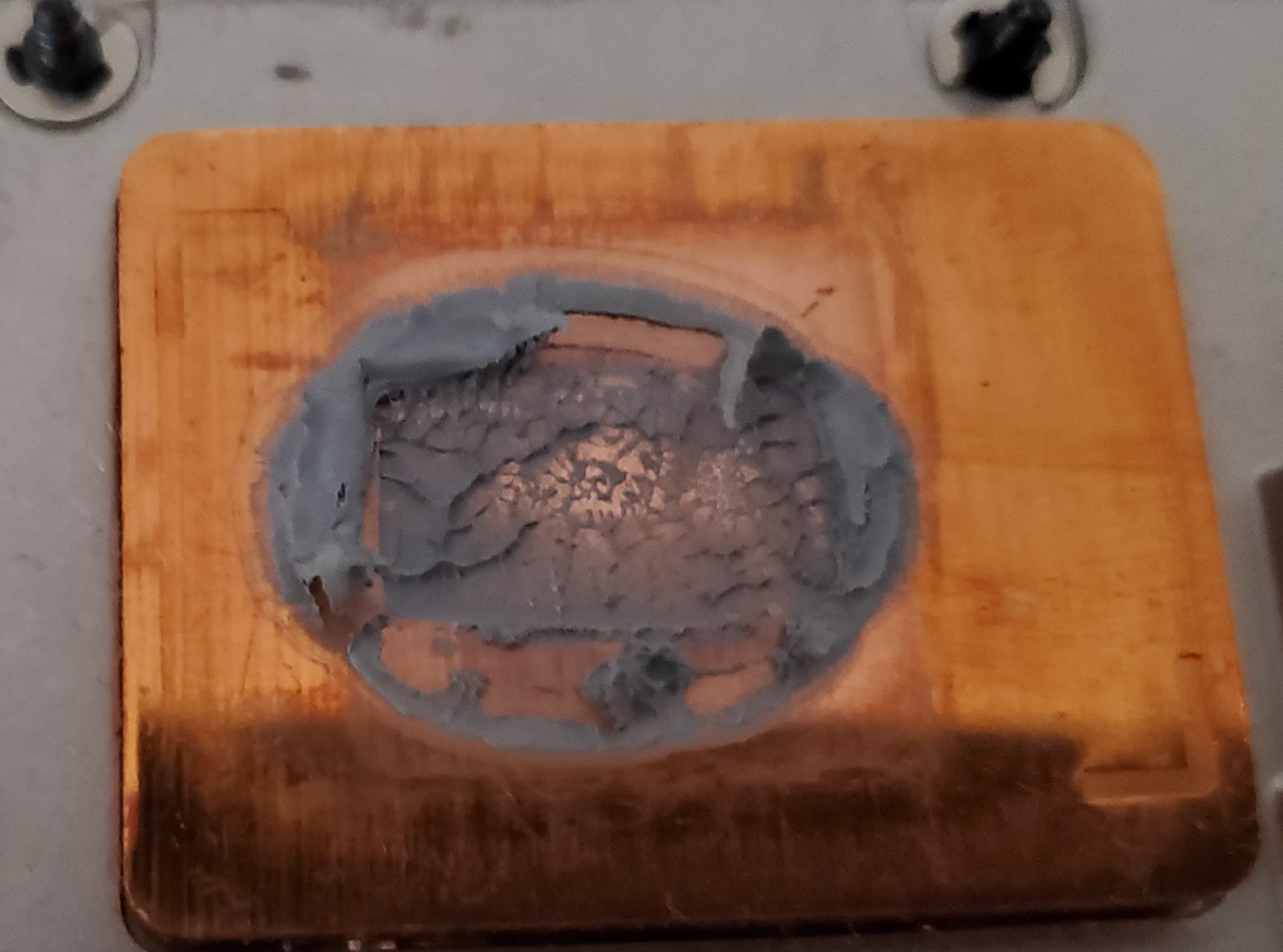
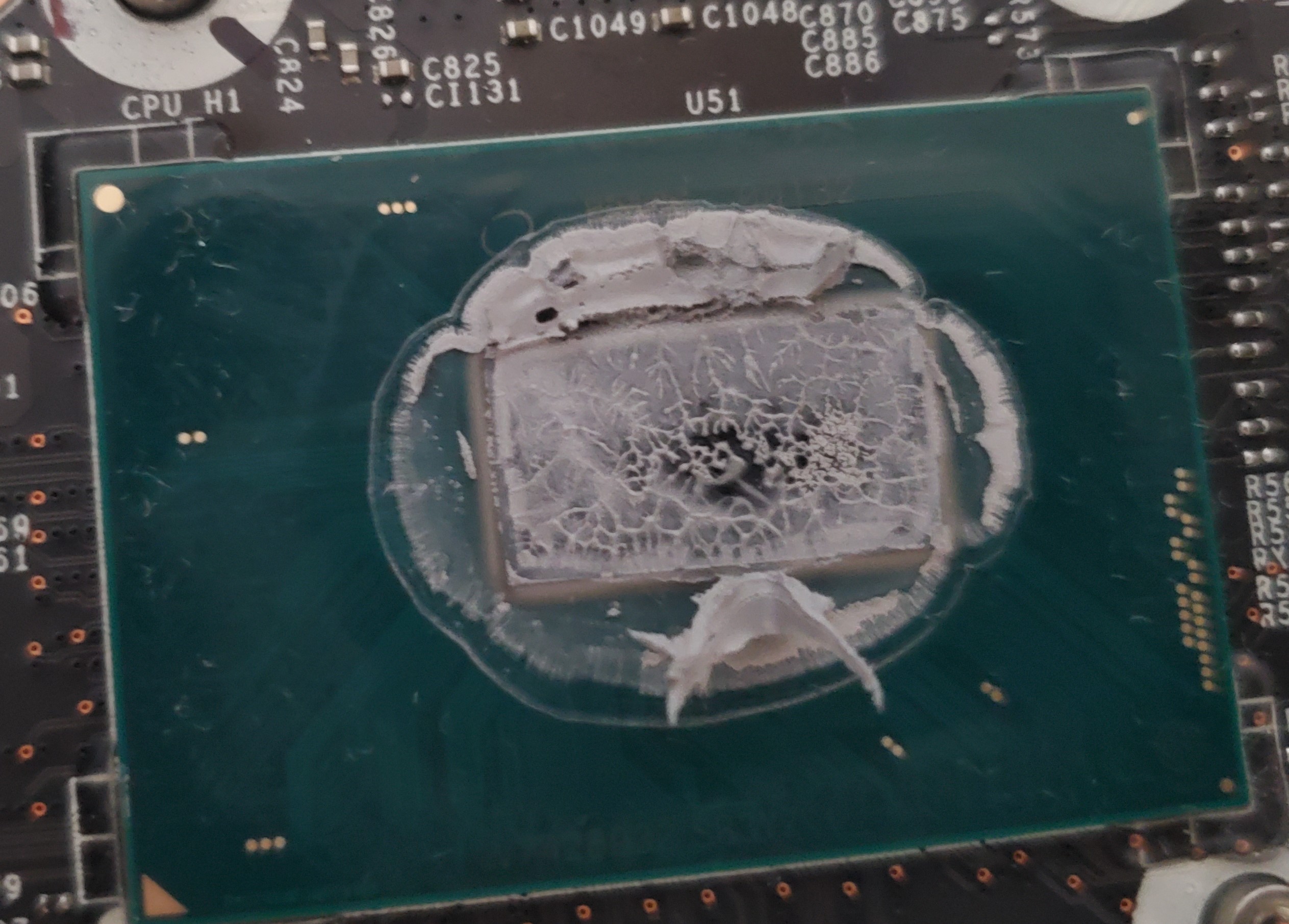
Here's pics of the heatsink and die after I took it off just now. There's a spot right in the middle of the die and on the heatsink where it makes contact with the die that appears a little emptier than it should.
Attached Files:
-
-
Emptier means higher pressure.
That pattern shows a -very- domed surface. Either that chip is convex as hell or the heatsink is convex. Looks like there is too low pressure on the edges of the chip. Pressure paper imprint is going to be interesting for sure. I would lightly sand the heatsink (you want to do as little removal as possible, making the surface flatter).Papusan likes this. -
Does it appear the paste is "pumping out" from that center area?
-
Yes, that's what pressure paper should show, hopefully.
If the pressure were proper and the heatsink/CPU surfaces completely flush, you should see an even amount of paste all around the core, and an even, very small amount on the heatsink in the shape of the CPU, with most of the paste pushed out the sides. What's left would be in a rectangle with a roughly even amount all around it. In your picture, you see a large amount of paste around the outer edges of the CPU contact area and a lesser amount in the middle. This points to a combination of VERY low mounting pressure and a convex surface at the same time.
A washer mod will definitely help massively with the mounting pressure (you will need to remove the C-clips from under the heatsink) and then you will need to slightly flatten the surfaces for less convexity, with very mild sanding (maybe a pass of 400 grit--800--1600--3000 in that order).
But do the washer+c-clip mod first.
Here is a closer idea of what it should look like.
Even this isn't perfect because this is an ampere (3090) GPU and we all know how unflat they are. But clearly the contact is much more uniform than your picture, and higher pressure (less paste on the heatsink's contact area).
Last edited: Aug 24, 2021Rooter1234, Papusan and tilleroftheearth like this. -
Hey all, so I've read through a lot if the thread and was wondering what thoughts you all had. I'm planning on repasting my desktop GPU (2080ti FE) and my XPS 15. I still have some TG Kryonaut (non-extreme) that I could use, though I probably don't have enough since I need to use for a repaste on my desktop CPU.
I see the SYY 157 has been mentioned a lot. Would that be a better application for the XPS 15? Or should I look into getting a Carbonaut Pad instead? For the GPU, what would be the best option: Kryonaut, Carbonaut, or SYY?
Thanks all! This thread has helped a lot in my paste search. -
I was impatient so I just put on 1mm washers I had lying around and reapplied TFX again instead of switching to ICD7. So when the pressure scale paper arrives and I figure out what I need to sand the heatsink, it'll still be a quick and easy clean-up and then next time I can try IC Diamond 7. The CPU die already has some scratches on it so I don't want to wreck it with ICD7 just yet.
So I did my fat blob of a line method again and temps are cooler than any prior repaste job. I tightened the screws all the way. It was actually difficult to get the screw or the bottom panel in (the one next to CPU). I had to push around the panel a bit to get it to catch on the screw hole.
Here's to hoping there's no pump out this time anywayFalkentyne likes this. -
I used SYY-157 on the laptop GPU and had no problems (yet, knock on wood). Honestly, the pad is not a bad option if you are not overclocking your laptop CPU. I'd have done that myself if I weren't overclocking mine. I also have never had problems with IC Diamond on laptop CPUs so far.Jff007 likes this.
-
There will be pump-out. Your surfaces aren't flat. Careful about putting maximum pressure when there are hills and valleys on the chips. You can literally break them.
-
I'm running with an undervolt on the GPU and CPU for the laptop. XPS line is not very overclock-friendly, as is.
-
The cooler temps are expected (and very welcomed!) and so far proves that you had terrible mounting pressure. The amount of paste that was on the core, even in the center, means that it wasn't being pushed out and there was very little heatsink to die contact (of course there was some but it was very low). And on the outside of the core, there was no direct heatsink to die contact whatsoever, which is why there was so much thermal paste there! (Otherwise it would have been pushed out).
So now just kick back and wait for what happens while you wait for the Pressure paper to arrive, and possibly your sandpaper kit and glass panes. It's always to do non permanent mods first (e.g. C-clip removal and washers can always be reversed and reinstalled, although reinstalling a C-clip that small would be rather tricky).
My guess is that the temps will rise over time again but will take much longer to do so (again, the convexity of the mount was obvious in the original pictures and won't just go away). Higher mounting pressure reduces the effect of thermal expansion and contraction. It still happens of course, but it just takes longer for things to go south. -
He won't break the core. I've tested this enough to know already. The screws have built in stops anyway -they are not free turning to the end. If he turns the screw too far he will literally -break- the shaft from the head. This actually embarrassingly happened to me on my MSI laptop, and I can barely get (a spare, as I had two heatsinks) screw in there at all (part of the shaft is stuck in there from the old screw, thankfully it's not the entire shaft), but I did manage it (along with a ripped up spring from an old radeon video card stacked on top of the MSI spring, to help increase the pressure from inability to turn the screw very far due to the broken bit stuck in the mounting bracket. And even with that error I did two years ago, my last LM application lasted *two years* with 1C deltas, so I dodged a @Papusan vomit bullet there.
This is far different than direct die chips on desktop motherboards, or cracking cores with washers and excessive pressure on AMD video cards!
Yes I do agree he needs to do some sanding work. But as long as he has money for more thermal paste, there's no harm in testing this first before doing non-reversible mods!tilleroftheearth and Papusan like this. -
That pumped out quicker than before, though this time the temps stayed at or under thermal throttle range with fans on full. When I took the heatsink off, it honestly looked like a nice and even close spread everywhere. So the CPU or the heatsink must be convex I think. I haven't gotten the pressure paper yet. I may just sand it anyway.
Before I do, I tried out an IC Graphite pad for the hell of it. I had to put a tiny dab of paste between it and the CPU die to keep it still because it kept slipping all over the place. It seems to have settled at 90-91 C under normal fan profile on the hottest core which isn't great but definitely not terrible as it's not throttling. With the 100% Fan button, it stays at 86 C on the hottest core, hitting 87 sometimes but going back to 86 which is very nice. That's at 83-84 watts. It has a very good spread between the cores and also the coolest overall idle temps across all cores compared to the paste.
I'll leave it on for a bit to ensure everything's ok, then mess with the heatsink next time (and go with ICD7 after I sand it like originally planned). I need to order new thermal pads for the CPU, the old ones are just falling apart now. They're Fujipoly Extreme, but I don't know the thickness. Anyone know how thick the CPU pads should be? I assume any MSI laptop with a similar heatsink will have the same setup. The ones that are on there now look maybe 1mm. I was going to get 1.5mm Gelid Ultimate pads because I believe they're supposed to be squishy, someone correct me if I'm wrong? Which were the squishy ones? -
-
By the way, this is a little off-topic, but I noticed that no matter what I try in BIOS or XTU, I can't get the machine to maintain a stable non-full-load voltage. Like, it hits 1.17 or whatever Vcore when it's at full load, but when not at full load like when gaming, voltage will be 1.2-1.25v, which is excessive and obviously hot. It will even randomly thermal throttle while gaming. Not enough to impact performance, but the package temp spikes randomly even though the cores aren't getting hot enough to thermal throttle.
I tried setting it to Static in XTU, override in BIOS, etc and it seems to behave in Adaptive mode no matter what.
Anyone have an idea why? I don't want to hit the 100% fan speed button because that's excessively loud and I only use that for benchmarks or other things like that which I know will hit the CPU at 100% for an extended duration (like Handbrake). -
You need to set AC Loadline to "1" or "0.01 mOhms (Bios value divided by 100)" in the Core IA / VR settings in the BIOS. But this will turn off ALL loadline calibration from SVID. The voltage you see isn't voltage. It's VID. And VID is too complicated to explain here. This is best done when using "Static" VID rather than Adaptive VID.
Don't bother changing DC Loadline. This is just for reporting values. ACLL is the dominat value.
Note: Static mode on MSI laptops is funny enough, what Gigabyte calls "Override" voltage on their Z490 / Z590 motherboards, where you change VID instead of Vcore. (Fixed mode is the standard direct vcore mode). The difference is you can access Loadline Calibration at the same time on these boards, while on laptops you are at the mercy of what AC Loadline does to the VID at load. There is no way to set "direct" Vcore mode on any laptop (except possibly some clevos? But I think even Clevos use SVID, because if they didn't use SVID, they would have a section specifically for "Loadline Calibration."
For a more balanced value, you can use 60 for Core IA AC Loadline (this is divided by 100 in MSI Bios so this is 0.6 mOhms).
Left alt, right control, right shift, F2 simultaneously to access VR settings.Last edited: Aug 31, 2021 -
Thanks! That's super helpful. So that's what that does, lol. I remember doing that with most of my desktops when overclocking, but I didn't really understand why.
So with the laptop, sanding this heatsink was very annoying because of its weird shape. In one of the directions you had to use very short swipes because part of the heatsink comes down lower than the section which meets the CPU die. I think I would have had to do it for a long time since everyone was talking about like an hour for a desktop heatsink, which is kind of heavy, and long movements on the sandpaper. I didn't have that much time to spend just sanding a heatsink so I just used the finer grit sandpaper to smooth it out (the surface had imperfections in it which you could feel) a bit, then I tried something a little different:
I used a fresh cut of the IC Graphite pad, but without the paste underneath (I used a tiny pin to put a tiny drop in one of the corners to keep it stationary rather than a small dab from squeezing the tube, I didn't want the paste to have any measurable impact). I figured the temps were just a degree or two away from being optimal with the pad, so maybe that tiny dab of paste in the middle was too much.
I put in smaller 0.8mm washers all around (the 1.0mm washers were too wide to begin with and kind of rubbed against other parts of the heatsink, I had pulled them out of my laptop stand). I removed the E clips entirely. I put on the new thermal pads (1mm was the correct height, they matched the old one, and they were nice and squishy). I put on the heatsink, screwed it on turn by turn in the appropriate pattern.
Checked temps, very similar to before. Couldn't get that extra 1-2 C to come off Core 2. I'm guessing 0.8mm still left enough room for more pressure. 1.0mm would've probably dropped temps maybe another degree as I was looking for (so removing dab of paste from middle helped). But I didn't want to use those wide washers again.
So then I took out the top left screw (#1), put a second washer on it (so it's 1.6mm). Checked temps, and now Core 2, the hottest core, was behaving a little better.
So then I tried screw 1 (top left) and screw 4 (bottom left) with double washers, and temps were better on some cores slightly, but core 5 suddenly started heating up with the others whereas it was the coolest before.
So then I tried Screw 1 and Screw 3 (top right) which dropped Cores 0 and 2 by a lot but now cores 1 and 3 were the hottest cores (basically swapped hottest and coolest). This gave me my first real clue that Cores 0 and 2 must've been on the top part of the die. First time ever that Core 2 ran very cool. Unfortunately Cores 1/3 were getting *too* hot.
Then I tried Screws 1 and 4 (bottom right). All the temps were slightly better than just screw 1 with double washers, which made sense, they were diagonal to each other. Since Screw 3 was the one where applying more pressure started to drop the temps on Core 2, I was going to put double washers on that and then play with how much I screwed it down, to see if I can hit a sweet spot where Core 2 would drop a few degrees but the other cores wouldn't overtake it. Well, on the very first run with all 3 (Screws 1, 2, and 3 with double washers but not Screw 4 on the bottom left), the temps on Cores 1, 2, 3 were now in a dead heat, and Cores 0, 4, 5 were together behind them by about 3 to 4 degrees. The hottest temp was reduced by about 2 C at peak without fans on full (about 86 C or 88 C peak depending on how laptop was oriented with space underneath or not... was about 89-91 C before). BUT, hitting the 100% fans button now resulted in all temps dropping to 85 C and even less after a while (dropped to 84 C, then even hit 83 C a few times after several minutes). Before it'd drop to 86-87 on Core 2.
So, this is acceptable. I also noticed that making the hottest core slightly cooler and the other cores hotter, made the heatsink/fan more important for dissipating heat. The faster the fans got, the cooler everything got. And in general all the stuff above just reinforced there was a problem with mounting pressure and the flatness of the heatsink and CPU die (CPU die was probably not flat going by what I saw).
Lapping everything perfectly and then using a good paste would've probably made temps perfect, maybe low-mid 80s at peak on normal fan curve without pressing the full speed button. But this works, and hopefully it stays consistent. The pad should last a very long time, ideally will never have to open the laptop again. Would also make for a good selling point if I resell, that it doesn't need to be repasted.
So my problems were:
1) Unable to confidently lap heatsink to a perfect flatness because of its awkward shape and tiny size. I also don't really know how to measure flatness either.
2) Adding to #1, being unable to lap CPU die. It was not flat either and mine had tiny imperfections in it, which also made me hesitant to apply ICD7 because that would only add more scratches if I had to remove the thermal paste again.
3) Unable to properly apply the perfect fine thin layer of thermal paste initially (but by the end I did enough applications that I knew how much of a line/dot to apply to cover just the die perfectly without adding excess like in the pictures from earlier)
So using the IC Graphite pad sheet fixed the application problem because the sheet is the perfect thickness for thermal interface material. That's why the idle temps are so low, this is ideally how much paste I would put on if I were good at it.
And then varying up the mounting pressure by messing with the screws (hypothetically you could just use stock screws and just vary how much you screwed them in, but overall mounting pressure was low to begin with for my machine) helped compensate a little for the non-flat surfaces.
I don't think you can do this with thermal paste, for what it's worth if anyone else is reading this for clues on what to do about a similar situation. You'd have to use a thermal pad on the CPU to experiment and figure out where the pressure needs to be increased, then once you figure that out you can remove everything, put on paste, then tighten it to the desired pressure. But you'd still have to use something like IC Diamond 7 which pumps out less (IC says its liquid content is in single digits, like 6-8%, which makes it resistant to pump out). Even TFX is too liquidy to not pump out under such conditions.Papusan and Falkentyne like this. -
So, dropping it to 60 (from 179) made the CPU able to achieve a lower voltage than before (at load) and thus cooler temps. Was that supposed to happen?
-
Yes it's supposed to happen. ACLL is a resistance value in milliohms (Asus boards use 1/100th values directly like 0.01, etc). The higher the ACLL value, the more the SVID (VID) is boosted at load (compared to idle). DC Loadline reports this value as a function of estimated vdroop. It's important to know that you can't measure vcore on boards without direct VRM access. You can only estimate it through VID.
On SKL, KBL and CML chips, estimating the proper voltage is difficult. You can get the "base" VID by setting both ACLL and DCLL (both of them) to 1 (or 0.01 mOhms) then looking at the VID in windows. This is the base voltage the CPU is getting at pure idle. Thermal Velocity Boost also affects this (this makes VID rise X number of millivolts every Y amount of celsius increase, which changes in degree depending on CPU multiplier--the lower the multiplier, the less the increase).
I have long forgotten most of this stuff but I believe the formula is (or was):
Vcore= bVID (mv)+ (ACLL mOhms * dI) - (Loadline Calibration mOhms * I) + vOffset.
Where bVID=base vid (e.g. VID displayed when ACLL & DCLL=0.01 mOhms or "1" in Gigabyte/MSI Bioses) + TVB increase
VID must be in millivolts, not volts.
vOffset=offset voltage (if you are setting an offset).
Note: Setting an "override" voltage on a laptop actually changes the base VID to that precise amount, rather than using silicon defaults. Setting an "offset" increases the base VID by the offset amount. You're normally not supposed to be able to set both an override and offset at the same time, but with the hidden Bios menus, in "Overclocking Performance Menu", you can actually do this, and then the offset is applied on top of the override "VID".
I= Current in Amps
dI=Loadstep current in Amps (dI=d1-d0)--difference in current change between two samples (dont ask me what this means, I do not know).
Loadline Calibration=fixed value of vdroop (this can only be changed in desktop boards by accessing the VRM directly, laptops you have no access to this anywhere).
I think this value was a fixed 1.80 mOhms on SKY and KBL and CFL 4 core CPUs, and 2.1 mOhms on 6 and 8 core CFL chips.
On Comet Lake (10900k, etc) and RKL, this became even more complicated because the CPU can can request up to a 200mv VID offset by itself (This is actually shown in Intel's specsheets, as 1.520v max VID + 200mv=1.720v (BEFORE VDROOP!!!!) technically, 9900k was capable of this, but I don't know if it ever used it, but both CML and RKL chips definitely use this), and when I was testing VID on 10900k under NDA (before release, with an ES chip), I was unable to get an accurate VID with the formula anymore. It kept acting like the AC Loadline amps was cut in half or something with VID no longer being capped at 1.520v.
Again please dont hate me for not giving you the information you want--I don't even remember if this is accurate anymore!
Basically, ACLL raises the VID at the source (before the VRM)
Loadline calibration drops the vid (vdroop) after the source (output voltage). Normally ACLL and Loadline calibration are the exact same "default" value unless you change one of them (ok, basically, they seem to be inverses, doing the opposite thing), but this isn't completely accurate as they act on different parts of the input source, which could actually cause internal CPU voltage to drop drastically during very large load, before ACLL is able to "boost" the voltage to compensate for the drop (remember I mentioned "Load step?"). When I tried using direct SVID on my desktop (9900k at the time) to use AC Loadline instead of increasing loadline calibration (leaving LLC at 1.6 mOhms, intel's default value, and setting AC Loadline also to 1.6 mOhms, also intel's default value), when I tried loading Battlefield 5, it would BSOD rather quickly right after launch, because ACLL was unable to boost the internal voltage fast enough to compensate for the giant load step (from BF5), causing Vcore to drop super low just enough to BSOD. While a balanced, sustained non-bursty load like Cinebench R20 would run just fine as the load step wouldn't be bursty.
This is all i remember. Sorry if that's not enough.raad11, MyHandsAreBurning, Papusan and 1 other person like this.
Which Thermal Paste to buy and apply (Traditional and Liquid Metal)
Discussion in 'Hardware Components and Aftermarket Upgrades' started by Vasudev, Jul 11, 2017.