So you adjust the fan speed in BIOS?
-
Is it only for fan control?
-
Yes, its mainly for fan control. You can set new trigger temps as well as adjust hysteresis values for how quickly your systems ramp up to the new fan speed at each trigger point.
-
So when i use -> Core voltage offset (-219.7 mV)/cache voltage offset(-110.4 mV) If i can get into cod MW its like 6 degrees cooler over -110.4/-110.4 settings which are manageable.
But im crashing lots. Honestly any Core voltage over -110.4 is causing it. Am i missing a setting here to have success?
The crash itself is over some great heat buildup quickly- like something on the chip wiggs out, soft lock and on reboot temps are over 90. Use cool boost reset throttle stop and back to square 1. unsure whats going on. -
You shouldn't copy someone else's settings as each CPU is different, so you may get an unstable system if you use someone else's settings.
With that out of the way this is how I would determine the best undervolt for your individual system. Initially start by gradually increasing both your core and cache voltage offsets by the SAME amount. Test for stability and keep doing it until you get an unstable voltage offset. When you reach this level reduce it by 5mV so that you are stable again. Once you are at this point I would gradually decrease ONLY the core voltage offset. Again do it in small incremements and test for stability. Keep doing this until you are either unstable or your core voltage offset is DOUBLE the value for your cache value offset(as you don't gain any further improvements when going beyond double the cache voltage offset. If its the former backtrack by 5mV and you should have the best stable undervolt on your system. -
Hey there, I'm looking for a vBios for a 2080 max q that is the 90w version, so I can update the 80w version I have in my GS66. Anyone have an idea where to look?
I'll be down to pay whoever can find me a working version of the 2080 max-q 90w. vBios. Thanks!Last edited: Jul 19, 2020 -
Talk to @JRey he did it on his
-
I have the 90w 2080 Max-Q, not the super version.
I’d check in with the GE66 group, that should be a 90w version since it can dynamically boost to 105w.
Sent from my iPhone using Tapatalk -
Is the 2080 super in the ge66 confirmed to be the 90w variant? My local store has one in stock and I wouldn't mind getting it to compare against my gs66 or maybe end up keeping both....
-
sucks they dont have it for the 2070 super....those are max p i believe
-
I've also checked around and every single 2070 Super Max-Q bios seems to be variable. In other words target power limit is 80W for all variants I have seen so far. I haven't found any single one that has sustained 90W input.
-
Looks like the GE66 does come with the 2080 Super Max-Q 90 w variant. I think i'll pick it up tomorrow or over the weekend and see how it is. Once I get the vbios I'll share it here.
Arkhaic likes this. -
I been doing this a while, so I cursed your name for such a bottom b low tier suggestion.
Of course, i then followed your advice and realized my core cache only barely tolerates -110v and was my entire issue. With that corrected and settled in at a conservative -100mv, now I am baby stepping the core voltage down down down to see how close to -200 mv the core will tolerate.
Good call, all the karma in the world to you. I couldn't see the Forrest for the trees. -
I would definitely like to try that with my GS66.
I'll run some thorough benchmarks and hopefully there's more than a 5% gain this time around versus the GS65 90W flashing. -
I'm curious but has anyone shunt modded their GS66? What strength of a resistor would I need? I'm new to this, so sorry about the noobish questions. Would a more conservative pencil mod be better? I just want it to pull power in the 90-100W range(Even with a conservative fan curve temps should be under 80C for the GPU with the higher power limits, with Coolerboost on temps would be under 70C for sure, at 80W I'm seeing 61C with Coolerboost on in a 80F room).
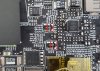
There doesn't seem to be any vbios available for the RTX 2070 Super (device id: 10DE 1E91) that have target power limits set at 90W. The Razer and Aorus vbios for the RTX 2070 Super all have variable power limits with target power limit set to 80W, so I thought a pencil/shunt mod might just do the trick. What do you all think? I've also included a picture of the board without the heatsink on it.
https://imgur.com/a/iLCdqSv
Where exactly is the shunt? I can't find it like you can on the desktop cards.
https://www.gamersnexus.net/guides/3185-how-to-short-shunts-on-gpu-for-better-overclocks-titan-vLast edited: Jul 27, 2020 -
Shunts should be here, take a clearer picture of them so I can confirm.
A pencil mod would be really hard to do on these kinds of shunt resistors. So is stacking resistors. The only thing you can do is to buy 3 mohm shunt resistors with the same package size and replace the stock ones. -
It says R005 on them I think based off this old picture.
This is the best picture I have currently. I'm running experiments on my laptop right now so I can't open it up to take closer pictures.
-
-
Since the GPU has quite a bit of thermal headroom on the GS66 and a gigantic heatpipe being cooled by 3 fans, you can connect the heatpipe on the CPU with the large heatpipe on the GPU to relieve some of the heat generated by the CPU. This should be beneficial for those people who still want to use non-conductive thermal paste or are still hitting thermal limits using liquid metal, specifically the i9-10980HK models.
With Coolerboost on and running Cinebench R20 in a room with an ambient temp of 78F(25.55C), my CPU hits a max core temp of 77C with a CPU package power draw of 73W. Previously without the bridge connecting the heatpipes my CPU would hit 84C, again with the same settings.
Excuse the mess on the heat pipes. That was cleaned up after taking this picture, lolz.
I mainly used a 1x9x100mm copper heatpipe from here
https://www.ebay.com/itm/1-9-100mm-...776652?hash=item52345c360c:g:ej4AAOSwnIVdJW~N
You can buy it cheaper from other sellers, but this was the only seller whose item would arrive in 2 days.
Underneath the copper heatpipe I put down some Gelid GC extreme before laying it onto the heatpipes on the CPU/GPU. And its held down on the sides by some thermal glue
https://www.amazon.com/GENNEL-Condu...1&keywords=thermal+glue&qid=1596074920&sr=8-3
I also used some Kapton tape on top(not in picture) just in case, but isn't really necessary. I'm just overly cautious. There are of course better ways to do this, but this is just a quick and dirty mod.Last edited: Jul 29, 2020 -
These SHOULD be the correct shunts, they are the same ones used on my gs75. There arent any other pairs of R005 shunts found anywhere else on the GS66 right?
-
I think those are the only ones. Couldn't find any more of those.
-
Then it should be safe to go head with the shunt mod. Be careful, dont melt the solder onto the tip of the soldering iron then put it on the shunts, it will result in a cold joint. Heat up the existing solder on the pads and when they are liquid, melt more solder directly onto the pads and when its slightly taller than the shunts, drag a thin line of solder across.
And most importantly, let us know the results
-
Thanks for the advice seanwee..
I think I'll wait a month or so before I do the mod though. I want to have a bit more practice with soldering before I do this.
I've also been saving to get a good digital soldering iron. I've been looking at the Hakko-FX888D.
https://www.amazon.com/Hakko-FX888D...=digital+soldering+iron&qid=1596734479&sr=8-8
Also what mixture soldering wire should I get? I see there are 60-40 and 63-37 mixtures. -
Any solder will do
-
Get 63/37, thats eutectic that means that the transition state from liquid to solid happens in a very small difference in temperature, this allows you to solder easier and without as much risk of having cold joints.
-
Thanks. I will do that then.
-
Another quick question. I noticed that there are two paths going into each resistor. Across which ones should I solder a resistor across? The areas circled blue or the areas circled red?
Also, I was thinking of soldering on 20mohm resistors. The total current afterward passing through the card should then be limited to 100W. The only thing I'm unsure of is the power rating and where I should buy these resistors from.Last edited: Aug 7, 2020 -
That's a Kelvin connection on the shunt resistor, both the red and blue are part of the resistor, but you should bridge it on the blue side because that's the side that carries the power, the red side is used for the monitoring circuit.
Those look like 1206 inverted shunt resistors. You can find them on mouser, digikey, tme, rs, Farnell.
Are you in US, eu, or other?seanwee likes this. -
Like this
-
That is an inverted footprint, you need to cross the shorter dimension, not the long one.
If you want to just bridge, this is the orientation of the bridge:
 Last edited: Aug 7, 2020
 -
I just bridge along the entire shunt. Desktop shunt mods are done that way and it works fine.
-
If you do that on that resistor you are not shunting anything, the resistor is wider than is it longer, thats what I'm trying to say.
-
Oh I see what's going on.
If you look closely there is a thin green line bridging the shunt. That's what you need to do to successfully do the shunt mod. If you make a thick bridge across the shunt resistors it will trip nvidia's built in protections.senso likes this. -
MSI GS75 Stealth 9SG (LM)
Core i7-9750H (bypassed power limit)
CB R15: 1324 || CB R20: 3244
16GB x2 DDR4 3200 CL18 (OC) Samsung C-die
RTX 2080 Max-q (Shunt modded)
Firestrike graphics: 26321 || Timespy graphics: 10030
Samsung PM981 512GB x2 Raid-0 + 1TB WD Blue M.2 SSD
why are you running raid 0 speed at that level does nothing for usage and 1 tb is nicer than 512gb -
Well, I have since unraided them (it's a pain to setup raid when installing windows) switched to just using 512gb + 512gb + 1tb
And what do you mean by 1tb is nicer than 512gb? The laptop came with 2x 512gb ssds and I just added a 1tb for bulk storage. -
I decided to RMA my gs66.
Due to the speakers and displayport not working over thunderbolt3.
MSI had it for one day, opened the box, and sent it back the same day.
It's supposed to be delivered on Monday.
I suspect they didn't fix anything. -
I'm using RAID0 on both my GT72 and GT75, just make the RAID0 array in BIOS and windows just picks it up as one drive, never had a single problem installing windows on the RAID arrays.
-
I've always had to do some driver setup and drive partitioning when installing windows.
-
Drive partitioning is up to personal preference, I always use my disks(be it HDD, or SSD) as whole, dont like to break them up into multiple drives, but never had to load any drivers.
Unless you use Win7, then you need to indeed make an image with the USB and RAID drivers or it wont even start installing. -
I got these resistors to solder on
https://www.mouser.com/ProductDetai...40t6SqHNONg==&countrycode=US¤cycode=USD
0.040 ohm through-hole resistors. Hopefully, the power rating is high enough and won't cause any issues like burning out. -
40mOhm in parallel with the 5mOhm resistor gives you 4.44mOhm, at least go for 20 mOhm resistors, and doubt you will be able to fit those leaded resistors in there.
-
I might try at most 0.03ohm resistors. This should keep the overall power draw near 93.3W. I don't want to be overzealous and unnecessarily stress the other components on my motherboard. This is my first time doing this type of mod which is why I decided not to do 0.02 ohm resistors because it would put my max power draw closer to 100W.
-
Finished the mod. Ended up using these 0.030 ohm resistors from Panasonic.
https://www.mouser.com/ProductDetail/panasonic/erj-8bwjr030v/?qs=KH2o3k57USjRDkVeN5PTHw==&countrycode=US¤cycode=USD
Will run benchmarks over the weekend. First time soldering so be gentle with the comments about the solder job, I know it could be better.
seanwee likes this. -
Hahaha that does look janky.
A better way to solder it would have been to just place the 0.03ohm resistors on top of the shunts and extend the solder upwards until it connects with the resistors.
Keep us posted on the scores
-
I did try that initially but it was just really hard to get it to get in place properly. The solder would constantly try to creep onto the resistor on top and disconnecting from the one on the bottom. Maybe with more patience, I could get it to work, but I had already tried that for an hour with no luck and got frustrated. That's why I resorted to this ghetto arrangement.
At least this way the two resistors can dissipate heat a bit better than to fully stack them parallel to each other.Last edited: Aug 17, 2020 -
Apply a blob of solder to each end of the resistor first, place it on top of the shunt, then melt and join both of them.
Resistors dont generate much heat in any case. -
I also tried that, but still had the same issues.For some reason the solder would still end up leaving the bottom resistor and pool up on the resistor on top. Its most likely some issue with my technique that's causing these issues. I'll try to practice it on some older GPUs I have laying around next time.
-
I also had another question seanwee. But based on the layout of the motherboard on the GS66 and the vrms do you think it can handle 100W on the GPU. I'm still learning about all these things and wanted your advice since you seem to be familiar with how these things work. I'm still trying to learn and understand all these things.
-
You needed more flux, when soldering SMDs, always flood everything in flux, and when in doubt, add more flux.werdmonkey4321 likes this.
-
This is after the shunt mod. Here are some quick and dirty scores with Time Spy and my RTX 2070 Super Max-Q. MSI Afterburner OC Scanner and +396mhz on the memory.
Attached Files:
-
Presenting the All-New Intel 10th Gen MSI "GS66"!
Discussion in 'MSI' started by -=$tR|k3r=-, Apr 2, 2020.