Sweet - I have a folder for you now too:
http://www.robsnetworks.com/toughbook/NR Contributing Members/ohlip/
-
Teo... Did you mold that or is it a straight cut into the corner.. Or just molded with a heat gun or boiling water?
-
The white trim portion of the antena is shrinkable tube, just extended a bet to look bold/slic all the way down to the cable beneath and the corner piece is the original one on which I thin down at the back area portion by a dremmelling where the antena will be mount and it expand when the sarantel antena passthrough to it and it give a nice clean looking setup. But be carefull on thinning the corner piece, you can feel it if it is good enough.
teo -
Very good.... I thought it looked a little different!
-
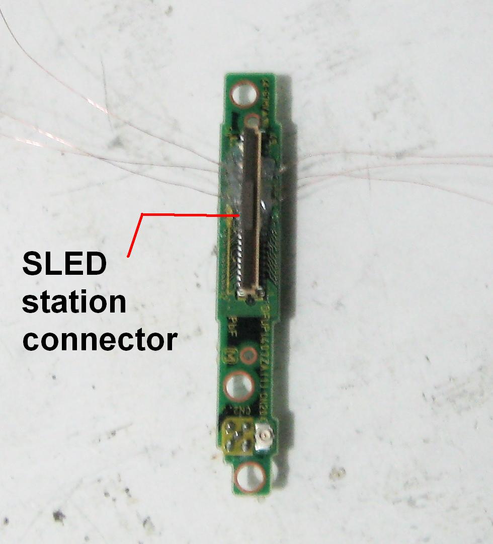
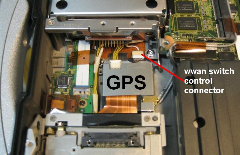
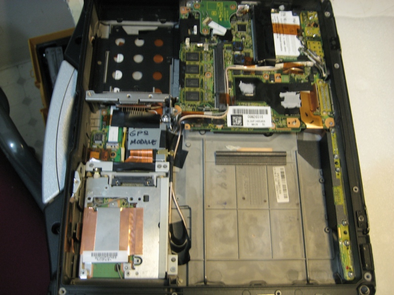
Ok! now is the time to reveal another hacked that i have created to my cf-29(1.6ghz). This unit has a built in WWAN untouch I mean as is(free) in short you can pull out the sled without affecting the gps setup but the difference is that I managed to installed the em408 on the unit not on the sled without taking out the sled. You can use the WWAN simultaneously with gps engine with no problem. Here are the story the pin out that I used is as the same as I previously posted on this thread directly to the CN18 but i soldered the interface cable for em408 on the sled station connector of the unit. Another difference is that the RF SW pin is located at the control switch botton connector 3rd from the MBO. area. The EM408 gps engine is located between the battery/sled and the harddrive caddy area. In order to fit the gps module on the said area you must taken out the patch antena of the module. Secondly loose the OEM ribbon cable and push a bet toward the harddrive caddy area and fold it whatever excess on the process even on the stationed connector side as well. Used an industrial double side tape for both the cable ribbon and gps module. See the complete setup on the photo below.
teoAttached Files:
-
-
Teo, Excellent post... Can you please post a few pics of how you ran and mounted the antenna? (I know where you went and pretty much what you did... But....) If you could post pics it would make it easier for others. I am assuming you ran the antenna that you bought from JDG that you posted above? (I just bought 5 of those BTW!)
Great job! Keep it up! -
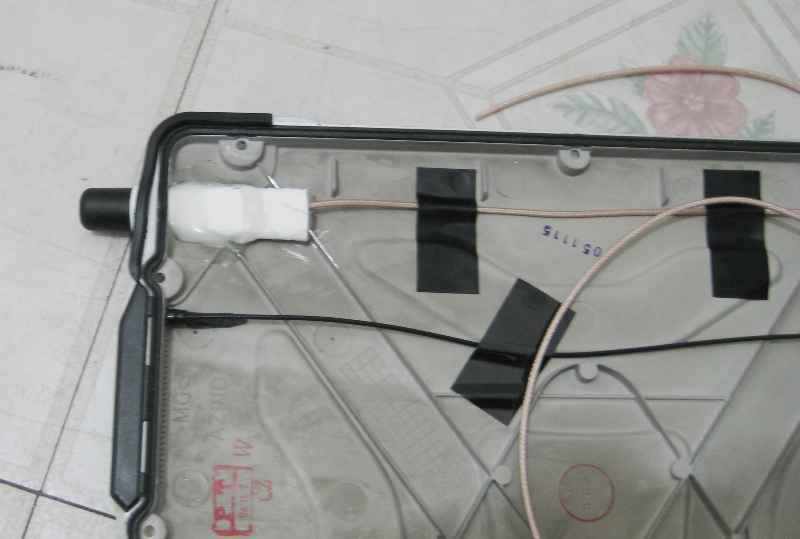
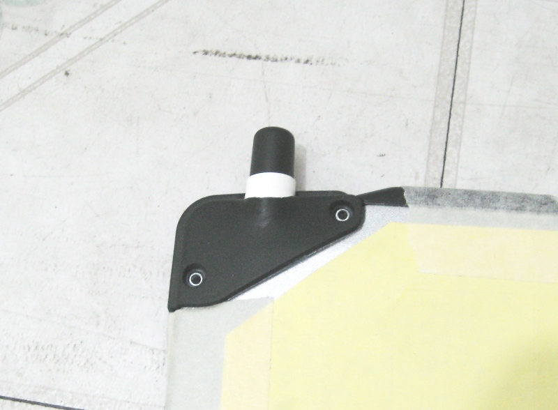
Ok! here is the complete photo from antena installation up to the final stage. Next time you will see it is on Ebay.
Attached Files:
-
-
This is so funny... We run them the same way... Down to the MMCX connector. Looks like you do the same thing. I take it you buy them in bulk? What about the lead cable? iS that RG-174? I bought 500 feet of it as I was tired of ordering it 25 feet at a time!
-
Good morning, everybody! waking up a bet late to much beer for the weekend. Hey! Rick, I used RG178 which is a bet good in diameter. As you said I still have I think 10' more and also a bunch of mmcx connector from mobile gps.
Lets talk about the funny part of mod.. is the installation of MMCx connector coz I don't have a crimping tool for the head cap( the lttle cylindrical cap cover). What I do is keep hammering on it till it goes down all the way but the problem is the the plug is full of wooden chip after the processed, so I need a needle to clear it out. Luckily it didn't damage the center pin of the MMCX connector.
How about you, do you have an special crimping tool for it. I keep looking on the electronic store but I can't find it, For the braided cap or the base I have.
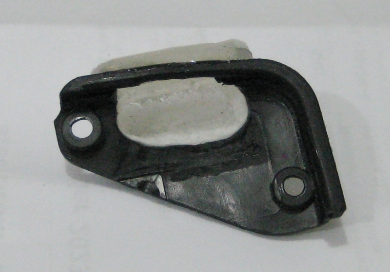
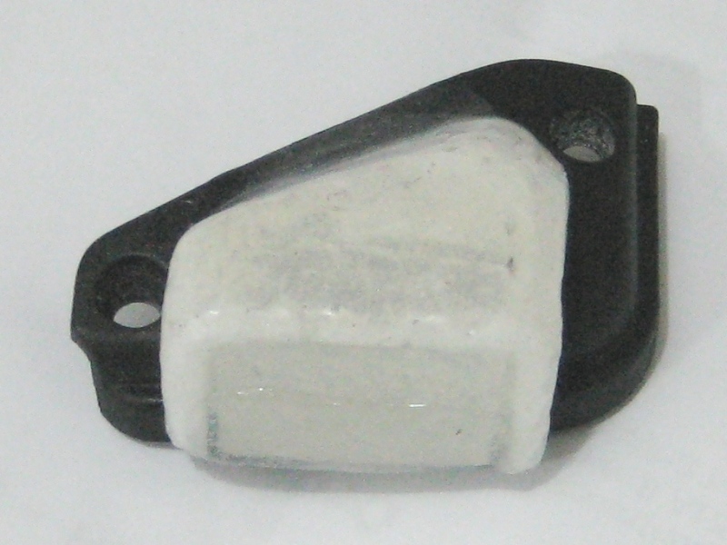
Ref. above: on the first pic. I applied a certain amount of quick dry epoxy (front and backside area) and when it ready for the rubber corner piece, I also apply a silicon sealant for inside and out to make it waterproof again.
teo -
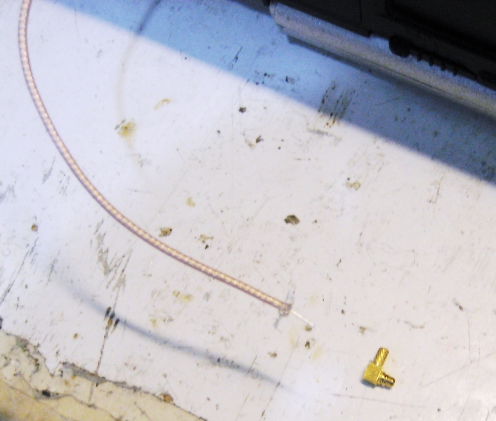
Teo... First I cut the cable end to size... Then I slide on two different sizes of heat shrink tubing. (But I don't shrink them until the last step!) I put on my smallest soldering tip and then lightly tin the tip of the lead wire. Too much solder and it won't go into the little slot in the center of the connector... Not enough and you then need to try to add solder in that tiny little hole! I used to do it that way... But if the tip isn't perfect it will slough off solder onto the inner side of the connector and can possibly short it out if sloppily done... Or you can get it on the side and either have to try to unsolder it or chip it away. If it is left on the cap may not seal correctly. We don't want that! So that is why I started tinning the end in advance.
Anyway... Once the center conductor is done... I cut the outer braid a little shorter and twist it around the outside and flow a bead of solder all the way around to solder all the braid to the bottom band with NO braid coming up to the head of the connector... Then I put the connector in a vise, lightly clamped, install the plastic insulator pad and then the brass cover. I use a drift punch to lightly tap in the cover... Then I flow solder over that as well to make it sealed forever! Then I pull the heat shrink tape over the soldered areas and shrink it down. I've never had one fail yet.
Oh... If you have already run your lead through the laptop... The CF-29 has lots of screw holes around the edge that accept the MMCX connector perfectly. Just make sure you don't tap the cover on too hard as it drives the connector down into the screw hole and can distort the ring around the connector plug.
Edit... By the way... Mobile GPS Online s WAY too high for brass connectors. These are things you may use for life... Buy in bulk and save money. You can buy 50 MMCX connectors from China for under $50USD... It takes a while to get them... But when you do you are set! I'm getting close to ordering for the 3rd time with them! -
I have no problem on the connector alone only on the head cap, the small brass after you soldered the center conductor that will cover it.Sometimes it jump out and nowhere to find, only by using mgnifying glass.
 I think there is an special crimper for that.
ohlip -
There may be... I've lost one or two.... But the thing is to have a steady base when you tap it on... If the surface gives the connector will "bounce" off and they are VERY hard to find on the floor! Try licking your finger to pick it up and then put it on the connector. There should be just enough spit to make the connector cap stay on without sliding off. If you have an 1/8" (2mm?) drift punch... They will not pop off!
-
U can find the necessary tool for the crimping of mmcx here: http://www.cablesupply.com/Products/Tools/CrimpTools/TerraWave/HT-336T.asp or if u look for the term "HT-336".
-
Hi All,
I acquired a CF-29 Mk3 a few weeks ago (to replace a CF-28 which in turn replaced a CF-27..)
I've been progressively upgrading it and am now looking at adding internal GPS and Bluetooth.
I have obtained (ebay) a sled complete with docking connector and the flex cable assembly, but the sled itself does not seem to match the info posted on here.
It has a single circuit board which I believe may be intended for a GSM wan module (though nothing is fitted).
The board has only the docking connector plus CN6 fitted.
CN6 is a 12 way which has 6&7 bridged, also 8&9 (power & ground?) - Is this the equivalent of CN3 in Ohlip's 'With Sled' pinout earlier in this thread?
For reference, the sled board also has positions for JK1 (Power connector through sled edge), CN2 (SIM card holder possibly, through sled edge), CN3 (40 way fine pitch), CN4 (22 way medium pitch), CN5 (6 Way medium pitch).
Board number is DFUP1301ZB(1), paper lable DL3U11301CAB D WGP291 4D.
Any info appreciated.
Thanks,
Robert Jenkins. -
Robert... Welcome to the forums.
This is for an "Aftermarket" GPS system. You can use the stuff you have but it is not plug and play... For that you will need to find a stock GPS system. Adding the aftermarket GPS is not for the inexperienced or for the faint of heart. You don't want to cross any wires when hooking it up! If you are handy at soldering and microsoldering then it's not a big deal. If you aren't... You may be better off getting a stock kit and adding that.
As for the bluetooth... The easiest way to ad BT is to get a BT PCMCIA card. But there are only a few that work. Billionton made the best but I don't think it is in production any more. It had a swivel antenna on the side. There is a much cheaper version with software that is not that great... But it does work. The card goes for around $30-$35USD on ebay and has a chrome pull-out antenna and an extra USB slot built into the card. What you want is a short card so it can stay inside and you can still close the port door/cover.
Hope this helps... You may want to peruse the CF-29FAQ too. -
Hi,
I am collecting bits to fit an EM-408 module or similar.
I was hoping to wire it as per the 'with sled' diagram by ohlip on page four of this thread, but the sled board I have has CN6 where ohlips notes say CN3 - I'm just hoping to find if this is the same pinout as the CN6 on mine, or even if CN3 was a typo.
For bluetooth, I'm going to base my on on the one by onirakkis here:
http://forum.notebookreview.com/showthread.php?t=242638
ps. I'm an electronics designer & used to working on surface mount gear etc. -
Sheeeeet... Then you won't have a problem doing this...
You can order the EM-408 from www.usglobalsat.com... Or click here....
http://www.usglobalsat.com/p-47-em-408-sirf-iii.aspx
You can take all the screws off the bottom. (NOT the hinge screws though!) and remove the bottom plate. **REMOVE THE BATTERY FIRST!** Take off the 4-screwed RAM cover, unplug the speaker and remove the plate. If you have a brown dog-legged ribbon cable coming from CN-50 then you have what you need. Any of the sleds can be made to work... You just need to find the pinout for which ones you want on the sled and that is fairly easy (tedious though) with a multimeter.
I find mine MUCH easier to do without the sled. -
By the way... I started using the active patch antennas that Teo suggested with a good copper plate ground plate and my results are almost even with the Sarantel Geo-Helix GPS antenna. So it is SO MUCH easier to install. I have it down to an hour or under for installation from start to finish! Depending on if I already have the bottom plate off and if I have a spare ribbon cable or need to remove and use the one that came with the laptop.
-
It sounds to me like what you may have is the PCB board for the sled that is used for an OEM GPS setup WITHOUT the EVDO modem installed. If you could post some pics, I could tell you for sure as I have both sleds. If you are not interested in the EVDO, then using Ohlips diagram to install the EM408 without the sled is the easiest, and best solution. IMO.
Hope this helps...
~~Paul -
If he has just the GPS... He wouldn't have the spring loaded SIM card thingy in the sled. At least mine haven't had one... He has a modem okay... I'm still betting on the Verizon modem...
Bueller? Bueller? -
The photo in this thread has the same sled board as in mine:
http://forum.notebookreview.com/showthread.php?t=323855
(First post, top photo).
The one I have is virtually a bare board (no ICs or topside connectors).
The only components on the top side are Q4, Q5 and a couple of resistors. Also no RF connector on the sled or harness so not intended for a wwan setup.
It certainly fits with this being from an original GPS-Only installation.
(Though I don't understand why someone would strip something worth hundreds of dollars just to get a $50 GPS module...)
It does mean I have the proper GPS antenna bump moulding - just hope one of the active antennas I've bought has parts to fit.
I fitted the internal cable & slide rail last night, I'm now waiting for the EM408 to arrive so I can make up the sled section.
Does anyone on here know what the original GPS module is in these? It must be tiny to fit in the gap under the sled main board! -
The GPS is hidden... Have you looked in the BIOS yet to see if the GPS is even showing up? The GPS engine is hidden under the pc board and is very small. he GPS antenna is actually in the very end of the sled and is very small also.
You may have a working GPS and not even know it.
And... Again... This thread is about adding AFTERMARKET GPS into the CF-29. I would suggest starting a new thread or finding one of the older ones about stock GPS in the CF-29 to continue this discussion. If we start shooting off in all directions then the info gets all over the place and people have a hard time finding the info that they need to fix/modify their laptops.
Thanks!
-
It's a basic sled with only a virtually bare carrier board - the GPS connector is fitted but empty, which is why I'm buying the EM408 & why I'm following this thread..
-
You can use the pin I posted for those with sled option on a 12pin hirose connector for gps. The only pain is soldering on the pin leg or you can do interfacing on flex cable with the em408 cable. Good luck.
ohlip
P.s. You can actually fitted in the em408 without taking out the patch antena on it as there a lot space without the WWAN option. -
Well, my EM408 arrived today so I made up a lead and fitted it to my 'sled'.
I plugged it in and was a bit puzzled the plastic end cover didn't fit all the way in place, but more concerned about powering it up and seeing it work!
Checked in the BIOS setup, I have GPS! Set it on & Com2, booted up and tried various programs - nothing...
---
When I got this sled kit I was puzzled why someone would remove the GPS module from a GPS-Only Sled.. Explanation? The sled board 3.3V power circuit is dead.
That also explains the mis-fitting plastic front, 'cos they kept the real GPS one when (presumably) they put their GPS into an old none-GPS wwan sled.
---
The regulator is just electronics, I can easily fix that.
The front moulding is another thing - it's almost a quarter inch out of position with the sled connector docked and the centre screw position tightened solid up to the sled metawork.
I'm guessing the real GPS moulding has a decent sized bump for the antenna? This one extends not much more than 1/16" beyond the line of the machine side at the front and flush over the (glued) SIM cover at the back.
Any thoughts?
Robert. -
I had the same problem. There are actually 2 different setups for that, each with it's own plastic piece. If you look inside the plastic cover, you should see a piece inside kinda like a stop that you can razor out and be fine. What you have is the plastic piece for a shorter PCB and are putting it on a sled that has a longer PC board, ergo, that "stop" is preventing the cover from going on.
As for your GPS, if it is showing up in BIOS, then your unit is good, the ribbon cable is good, and probably the antenna is good. The fact that you are getting no power tells me that the fuse is blown on the PCB. There will be a very small, most likely white, ceramic rectangular fuse with a 1.5v on it. You can pick up a replacement fuse and solder it piggy back on this one and be fine. I have done that to mine. Once that is done, you should be good to go.
Let us know what you find....
~Paul -
Actually... Having the GPS show in the BIOS only means that pin 40 on CN18 has been successfully grounded. What you need to see is the data streaming in your choice of GPS programs to ensure that the GPS is truly working. Then you can make sure the antenna is working. Don't forget the ground plane to make the signal REALLY pop!
I'll suggest again that you lose the sled altogether. It is not needed. You can solder your leads straight to the end of the ribbon cable and then coat the ends with a little hot glue to insulate it and to make sure none of the wires get pulled off. Of course this is a relative permanent installation whereas with the sled you could transfer it as long as you had a wireless ready Toughbook or you had an additional ribbon cable to install.
Just my two cents... -
Best posible solution also is to publish a photo of your sled front and back side. So that we know which area or connector that we are going to talk about.
ohlip -
Hi,
thanks for the extra info Ohlip, it is working!
I tagged wires on a various points so I could check voltages & signals while it was in the PC.
Everything was spot on, but the PC was not showing receive data.
It seems the Com port number set for the GPS in the BIOS does not appear the same within Win XP.
I initially had it set to Com2 then changed it to Com4.
At that, it appears as Com3 to a Windows program... Wierd..
My final problem is I need a smaller antenna. The one I have (stripped out of a mini mag mount active unit) fits onto the 'bump', but the signal dies as it goes the last fracion of an inch into place. It looks to be when the metallised surface gets too close to the metal machine body.
The next antenna I am looking at is a 'Taoglas AP-12A', a bare, active unit just half an inch square.
That should be here by mid week, I will let you all know how it performs.
Thanks again to everyone for the help,
Robert. -
It is sometimes wierd. You know for sure that you connected the gps engine correctly but when you scan the gps it says nothing or none but it is there. You know what? The irq assign sometimes used by other device but you can't see it on device manager that there is yellow mark. Its the resources and com port must be change.
Now I wanna know what pin did you used on enable/disable function of em408 to the four posible pin that I gave it to you except pin 10 of the hirose gps connector.
ohlip -
Hi Ohlip,
I never did trace it through, the added wires showed the GPS was getting power and working so I left it at that. I should really check it powers off if switched off in the BIOS...
Is there an on/off utility program like for WiFi / Bluetooth?
Robert. -
Robert
If there is in the bios a setting for the GPS on / off / auto
The auto setting will have it turned off normaly
It will only turn on when an application is using the gps port
Alex -
RJ.... Your antenna will work much better with a ground plane. I believe Teo posted some great pictures of the how-to. I've been playing with various sizes and shapes and think I've found the perfect size for the 29... But I don't use a sled.
My first shot at this was with the same type of antenna you have. It was a little too big but I was able to fit it in place. But there wasn't really much room for a ground plane so the signal wasn't that great... Acceptable but not great.
Just my two cents... -
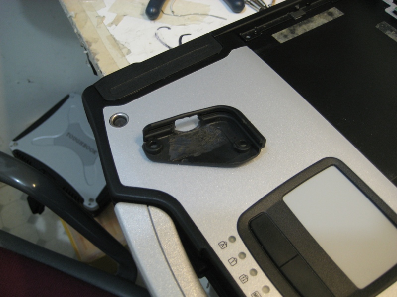
Its been a while and this thread must go to the top again. Here is the story: I am developing something that it might be the solution on gps installation to make it durable and slic looking unit CF-29 toughbook. Photo below will give you an idea of what I am talking about. If it is successful, I will make a mass production to sell it on ebay
since people now are looking for an alternative way to save a bet of money even myself due to this economic uncertainty.
ohlip
PS. and to stop cutting of fish
Attached Files:
-
-
Uh.... What is it? I assume it is an antenna mount? For which type? I assume that you would injection mold them and not have them white and black?
-
I don't understand it either
I'm thinking that there will be a different type gps antenna used
We will have to wait and see how this progresses
It looks like Teo is taking home the profits from his new job as is looks a little bit like sole fish filets
Alex -
Have you notice that! its a dover sole fillet. Lol
ohlip -
I have just pulled apart my 29 again (had 2 remove a bug from between the screen and plastic) any way I have found where the wireless antennas are so can anyone tell me what the extendable antenna (when the laptop is infront of you it is on the left hand side) is for
Thanks again
Sollybeans -
That is for the WWAN option. If you look in the BIOS it will show if it is installed. But a lot of these came "Wireless Ready" so that all you would have to do is to slide in the WWAN sled of you carrier choice and you could connect via wireless broadband.
-
Any status updates on this? It certainly looks intriguing.
-I'm currently using a Garmin GPS 18 (which works, but is just a bit goofy carrying around extra stuff.) -
Sorry! man, As I am to busy on my day job right now. I haven't yet started the casting and molding process. I will let you know when it is done.
ohlip -
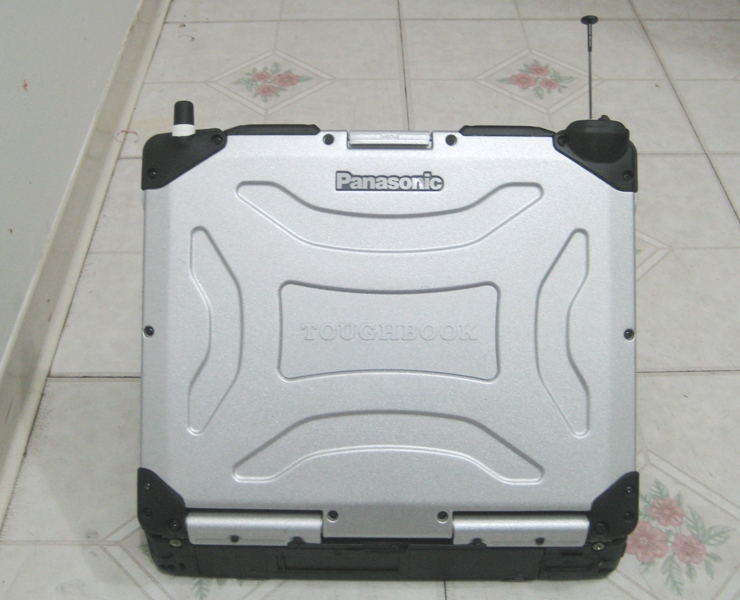
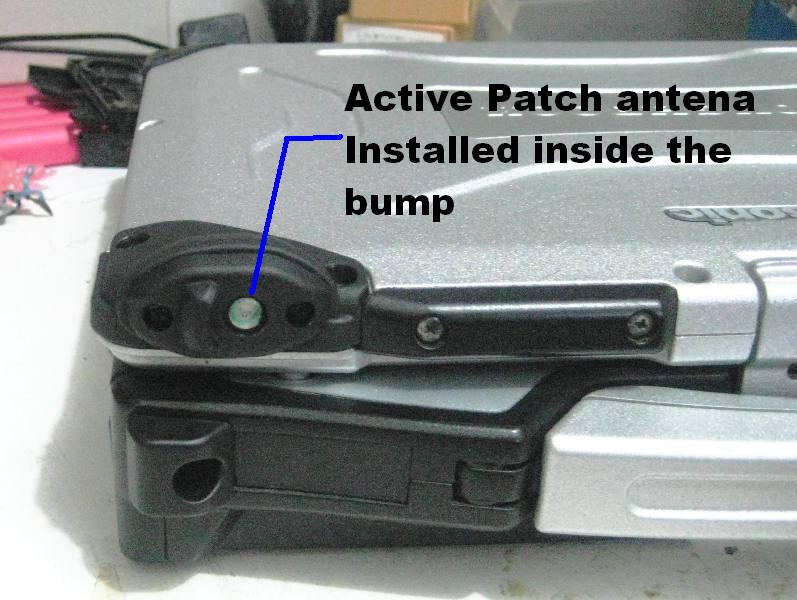
Instead of moulding and casting I installed active patch antena at the top of LCD where the WWAN antena located. I'll be on my original plan probably a month from now. Anyway, the setup that I made is beyond comparable to the antena that stick at the top of LCD. It is more durable and can take a bump ahead. Photo below is a final setup.
ohlipAttached Files:
-
-
I've been sliding an active patch antenna into the left palmrest area with terrific results. The only issue is if you are typing while using the GPS (Rare) then your hand may get in the way. It is in the stock position but uses much better parts.
-
Hey! Rick, Thats why i ended up installing the patch antena at the top of LCD so that not to interfer when you are using the keyboard. the work is very minimal compare to sarantel, no shaving of lid only the top hat cover of the rubber bump to fit the miniature patch antena.
teo -
Teo
Have you listed that cf-29 for sale yet?
I looked and did not see it for sale
Alex -
Alex,.. Not yet, I am waiting for a lot of DVD/Cd-rw combo that I puchased recently before I post to ebay. I already have the caddy for cd rom just the drive. I almost listed it on ebay last night with just cd rom.
teo -
Sheesh... Ebay sales... Don't EVEN bring THAT up! Everyone is complaining... Sales are down and ebay raises their fee structures and commissions. I REALLY wish there was another place!
-
Just came across a source for Garmin OEM GPS module! Maybe this would work well too?
http://www.gpscentral.ca/products/garmin/15lh.htm -
I deal with these people
Slightly better prices
http://www.gpscity.ca/item-garmin-oem-15-l-wired/oem15l-w.htm
Alex
Adding Aftermarket Internal GPS to the CF-29
Discussion in 'Panasonic' started by onirakkiss, Apr 18, 2008.