Attached are standard pinouts for USB Socket and USB Headers as used on MBs. The Socket pinout is self-explanatory; the Header pinout includes the standard color-coding as used on the wiring to the jack itself for front panel/ auxiliary rear panel connections.
As T2G says, industry standard design maintains this order of pins in almost every case; so once you find CHASSIS GND with your MultiMeter (it will be at one end or the other of the row of pins in question) you know where to start. Sometimes with 5-pin connectors there will be two GND pins next to each other; the extra pin is GND for the metal shield, then GND, then the pin next to that will be DATA (+), then DATA (-), then B(+) 5V.
Good luck,
mnem
Metered out...
-
Attached Files:
-
-
Dwagon, u'r right, if we would speak about an pc-board, but we are talking about an panasonic toughbook cf-29 mainboard
 u remember?
-
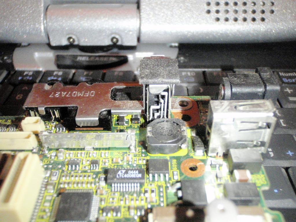
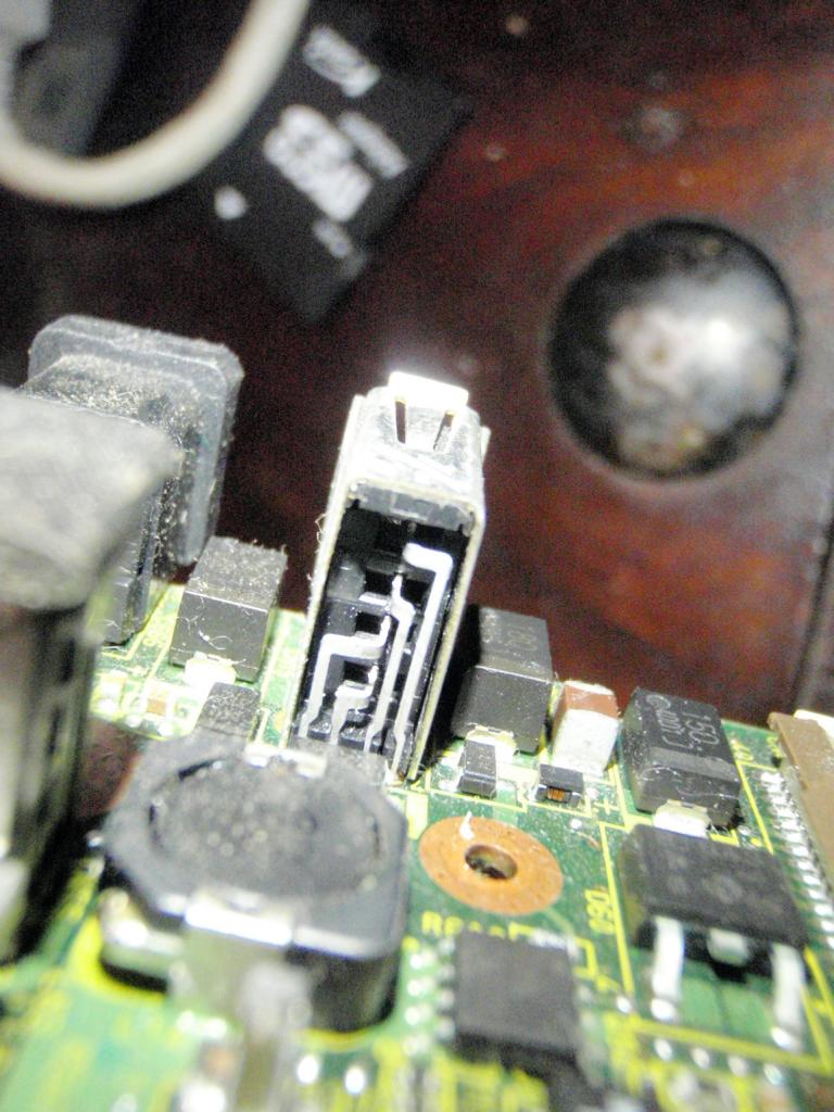
The only difference on the CF-29 MB compared to any other is that the USB port in question is installed vertically but I still see no reason why the connections would be inverted from the norm. I will ohm one out later to confirm.
-
...is one option, the other is u can have a look on the socket...
Attached Files:
-
-
I have hook up dozen and the color code is not a standard. The color I have list is right for these cams and will work. I have installed dozens of these just never hooked it to the usb port on the board as most people like to keep all ports open.
The best way to do anything is just get the pin out of everything your working on. This way you don't fry your MB
You can look at the usb port on a cf-29 and seen it's how i have listed. Just look at the back of the port they cross as listed. onirakiss started this and I followed so I'm sure we know what we are talking about.
The only standard is the port plug after that your on your own.
TB2010 -
T2G -
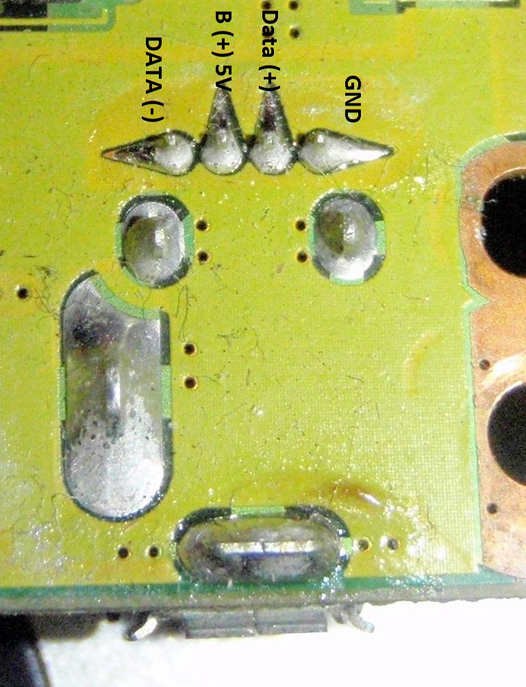
Onirakkiss is absolutely right; because of the oddball vertical orientation, the socket manufacturer has reversed the Vcc B(+) and a Data (-) connection. I'm looking at one on a spare CF-28 MB which has the exact same USB connector as in his photo of the CF-29 MB.
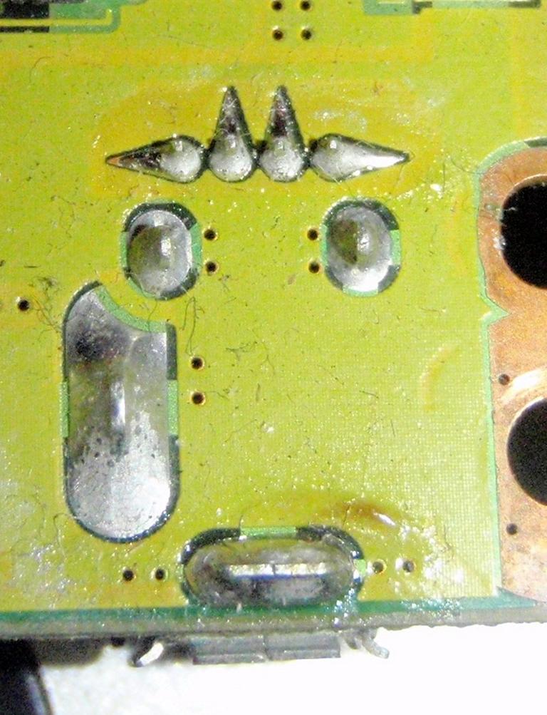
As it is NOW, the pinout at the back of the port would be thus: Data (-), Vcc B(+), Data (+), GND. See pic attached.
Onirakkiss, I stand corrected. In my defense, I DID say " almost every case".
Oh, and if you're wondering, I DID tone it out with my DMM to be sure. :wink:
mnem
" almost right"Attached Files:
Last edited by a moderator: May 8, 2015 -
-
my question has been answered. I supposed I fried the camera hooking it up wrong at some point, which is why it wouldn't work when I had figured out the correct way to hook it up.
Although I'm not an IEEE anything, I have fixed many cell phones, mobos, rear projection tv's, etc, on a component level....
so it turns out I'm only a partial idiot, not a total one.
I don't have the time, resources, or need to go get proper training. asking questions and trying things out is how I've learned an incredible amount of useful knowledge. I just lack certain important pieces of information sometimes, or need someone who knows what they are doing to tell me "yes, that's it" or point me in the right direction.
Thank you everyone for participating in the debate, and thx Onirakiss for the photo's and input. they cleared it all up for us.onirakkiss likes this. -
BTW, I've disposed of several laptops recently, and have found that the ffc that connects the trackpad touchpad to the mobo is the correct size and orientation for cn whatever under the kb....
I added a Webcam into my CF-29 :-)
Discussion in 'Panasonic' started by onirakkiss, Dec 9, 2008.