Thanks Meaker, after reading your comment I gave it another try today and realised what was (probably) the reason for the single-card no video issue: The previous owner of that X8100 had switched the position of the two cards at some point. The X8100 has its MXM slots labelled "master" and "slave", but the card in the slave slot was probably originally the master card (the crossfire cable end on the master slot, as well as the crossfire socket of the card that was installed in the slave slot had some minor residue on them, probably because they were initially secured with a sticker or piece of tape).
With the right master card installed in the master slot video output worked again. Since the random shutdowns persist I guess it is the NEC-Tokin then.
-
Did you try leaving the slave card out?
-
Yes, I left the slave card out. On my first test I accidently tried to use the Slave card in the Master socket (since I didn't notice that the previous owner had switched the two cards for some reason - master card was in slave socket, slave card in master socket, but video worked fine). So single-card video works, but the shutdowns remain. So I'm pretty convinced right now, that both graphic cards are working and it's the NEC Tokin I need to replace. So I wanna assemble a list of things I'll need for that.
Senso recommended 330uF 2.5V Capacitors with an ESR of 25m Ohm
https://www.ebay.co.uk/itm/4x-SMD-T...597050?hash=item362b5aadfa:g:JKwAAOSwAKxWXfB4
While Randomrat used 330uF 10V Capacitors with an ESR of 6 mOhm
https://eu.mouser.com/ProductDetail/KEMET/T530X337M010ATE006?qs=AaRlLUpeMsw53NLKZ0%2bwLQ==
The original NEC Tokin 0D108 seems to have been a 1000 uF 2V Capactor with an ESR of 1 mOhm according to this site:
http://www.lizbit.pt/store/nec-tokin/462-nec-tokin-od108.html
I'm no expert in electronics, but from what I found on the web the voltage stated on the capacitors specs doesn't matter too much, as long as it's higher than the original 2V (since it's more like a max voltage the cap can handle if i understood that correctly, so anything in the 2V-10V range is probably ok?). But what about ESR? And will 105°C max operating temperature be fine or is 125°C required?
Other than the capacitors I'll get some desoldering wick and flux to remove the solder of the NEC Tokin and rubbing alcohol and pads to clean up the PCB afterwards. I already got a 15W Iron, a heat gun, tweezers as well as an exacto knife and prying tool.
What method is safer to do? Heating the NEC Tokin with the heatgun until you can remove it with tweezers or prying off the chip?
@randomrat Which method did you use? -
The eBay ones work OK in core2duo based laptops, but it seems like the Clevo due to its beefier CPU needs the lower ESR caps, if you are buying from Mouser, I would grab the lowest ESR 470uF caps that there are available.
For removing the NEC-Tokin cap, my go to trick is to remove the plastic cover(easy to do, stab it in the middle with tweezers or screwdriver and the rest comes of easy).
Then, flux all around it, heat gun at 300ºC for 2 minutes, doing circular motions around the NEC, and with a hot iron, touch the solder that is around the NEC-Tokin, when it moves, grab it with a tweezer and its done.
Then, solder the new caps.Bratzi likes this. -
The lowest ESR ones on Mouser are 4 mOhm, but at 33,70€ for 5 pcs they seemed rather expensive, when the cheapest 5 mOhm ones are 13,05€ for 5 pcs. But when I wanted to buy them I saw that Mouser adds 20€ shipping cost for Germany, unfortunately.
Would any of these work too? If so, which one would you recommend to buy?
470uF, 2.5V, 6 mOhm ESR, 7343 Case, 105°C max (Part number T520V477M2R5ATE006) - 8,20€ + 3,52€ Shipping for 5pcs - https://www.ebay.de/itm/272967417294
470uF, 2.5V, 9 mOhm ESR, 7343 Case, 105°C max (Part number 2R5TPE470M9) - 5,44€ + 3,52€ Shipping for 5pcs - https://www.ebay.de/itm/273167850329
470uF, 6.3V, 8 mOhm ESR, 7343 Case, 105°C max (Part number 6TPB470M) - 8,46€ + 3,52€ Shipping for 5pcs - https://www.ebay.de/itm/273151851458
(Edit: Just realized the last one was 0,08 Ohm = 80 mOhm and not 0,008 Ohm. My bad.)
Also thank you a lot for sharing your desoldering tips! I'll use this method too then.Last edited: May 17, 2018 -
If you are in Europe, try RS and Farnell, as well as Conrad(German company), and TME.
Mouser shipping is free above 50€, but given that you dont need 50€ of components its a useless perk for you, all other companies are located in the EU.
10mOhm ESR:
https://www.conrad.de/de/tantal-kon...c-6tpf470mah-1-st-1179782.html#downloadcenter
Or the exact part number of your third link:
https://www.conrad.de/de/tantal-kon...-x-43-mm-panasonic-6tpb470m-1-st-1179768.html
I would settle for one of those, they are higher capacity and the ESR is in the same ballpark, 1-2mOhm can be easily lost/gained by how well/bad they are soldered. -
Alright, I ordered the parts as well as some flux, solderwick, isopropylalcohol and cleanroom wipes. Thanks a lot for the help, Senso.
I'll post an update with pictures of the process once all the parts arrived and I get to attempt the repair. -
Any doubt, ask before doing.
-
So the chips and equipment I need arrived today, so that I can finally replace this chip. I started disassemblying the X8100 today and did remove everything that was covered in the service manual ( https://www.manualslib.com/manual/1206694/Clevo-X8100.html). However there is no documentation on removing the motherboard.
In addition to removing everything that was covered in the manual (hdd, ram, cpu, gpu, keyboard, bt, wifi, fans, covers, heatsinks, odd, ledbar) I also removed the screws I indicated in the picture below. Motherboard still can't be removed, so there are probably still some screws left I need to find tomorrow. If anybody has an instruction/video/manual on how to remove the board I'd appreciate it a lot. I searched the web, forums and youtube for a mainboard replacement of an x8100 (/np8120 or m980nu/np9850) and didn't find anything. And the x8100 seems to have lots and lots of ribbon cables that seem rather easy to break :/Attached Files:
-
-
Check that no cards/parts are still in and screws hiding below.
-
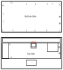
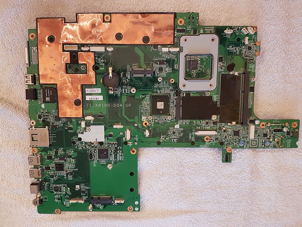
I've found the remaining screws and was able to seperate the motherboard. Man this thing has many connectors on it. I tried to document the screw locations and screw sizes if somebody finds this thread in the future. In addition to the images I removed the SATA adapters and every PCI mini card that was installed, but some of that is probably optional.
I also added two pics of the motherboard. There are some changes between the v4 and the v3 that's in the manual. Most ovious differences seem that a heatshield was removed and a PCI mini slot was added. If anybody needs a picture of a certain part of the motherboard, I can take some at this stage")
And here's the NEC Tokin chip (0D108). The CPU Backplate around it seems to be glued/siliconed on the PCB and it has small SMD parts around it. It looks much smaller than in the replacement guides I watched, which were mostly for Toshibas and had a chip 4x that big with no parts around and an easily-removable backplate. Should I remove the backplate or is it fine to leave it on?
This disassembly took quite a while and it's quite late here, so I'll continue tomorrow. Thanks for all the help!Attached Files:
-
-
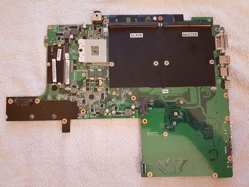
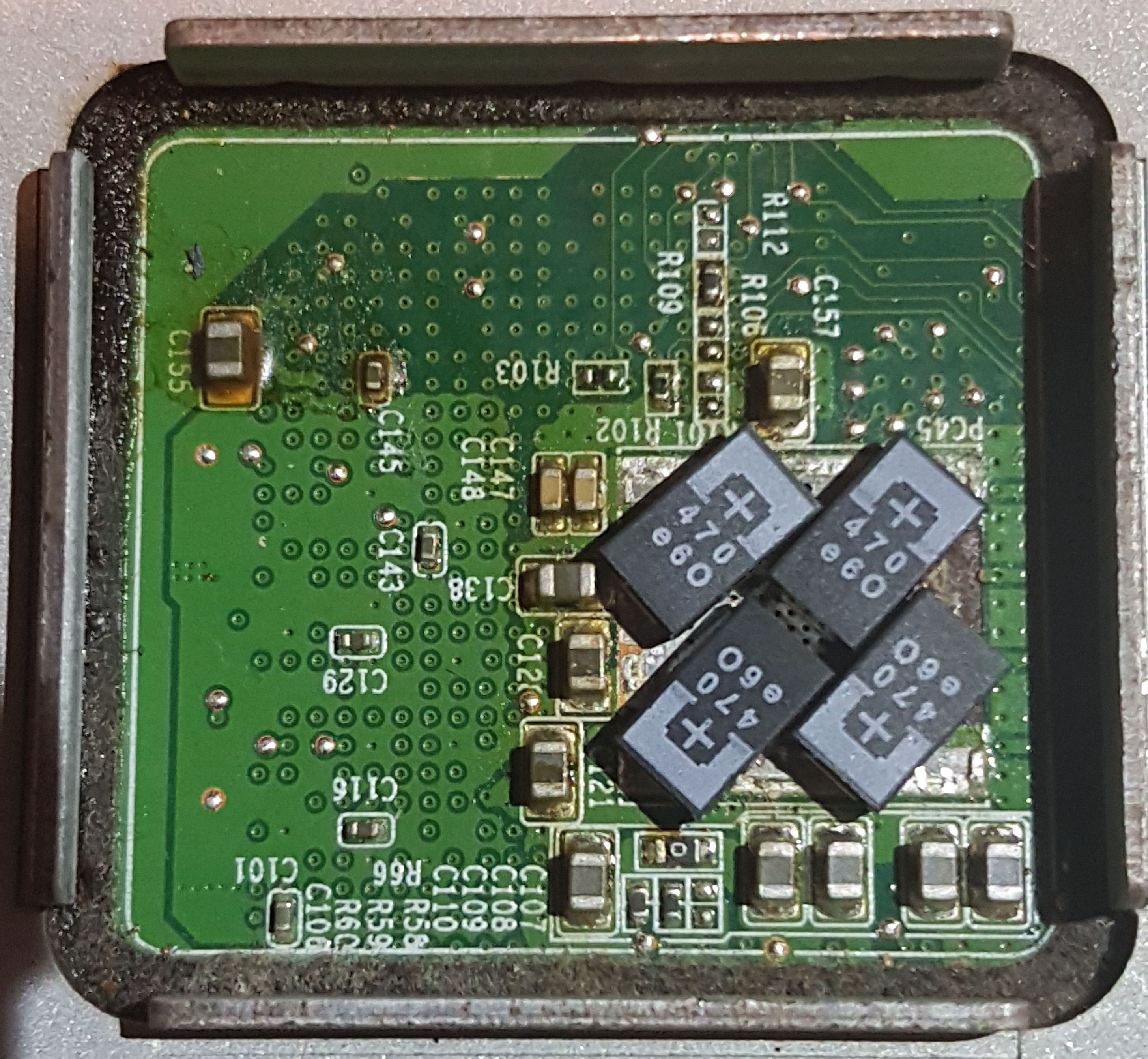
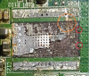
Okay, I tried to remove the chip and it started out alright. Only the center part of the NEC chip was the problem. The lowest layer of it seems to have been so stuck to the ground pad that it ripped parts of it off (It apparently has one large ground pad, instead of two small ones like on the Toshibas). Any suggestions on how to proceed from here?
Also the x8100's chip is much smaller than the older NEC/Tokins. There is barely enough space for 4 caps (see attached picture).Attached Files:
-
-
It looks like that metal shroud is tall, so mounting the caps side-ways will gain you a lot of space.
To rip that pad, you had to make a lot of force :/
Clean up everything, find cooper tape, cut more or less to the size of the pad, re-solder the couple tracks that connected to the center of the pad, then solder the caps to it. -
The ones circled in red are the ones that need to be connected, right? And the orange area should probably be treated with insulating varnish.
Do you generally think it's worth a try or should I just get new board? What are the chances of damaging other components if it goes wrong (mostly worried for gpus and the display, cpu isn't that expensive)Attached Files:
-
-
Yes.
Worst case you make a short-circuit and the cpu VREG will shutdown due to over-current, at most your CPU is at risk. -
If you have a multi meter I would buzz it out first.
-
Alright! Ordered some copper tape and a multimeter with continuity tester. Risking the CPU is okay. It's just a 720QM (~15€ on eBay). I was more worried about the GPUs, but I can probably completely remove those from the system for testing.
-
Handy thing to have, just don't use the multimeter on the mains unless it's a known brand and properly CAT certified
-
I went with a UNI-T UT139C multimeter for 36€ after I found several reviews/forums saying it's the cheapest they can recommend (while the issue with cheaper ones seems to be primarily safety concerns and not measurement accuracy). While the brand seems to have had some quality problems in the past, the newer models were reviewed to be well-built (at least that's what people said).
The copper tape arrived today; the multimeter will arrive later this week. Was there anything specifically to look out for when buying copper tape? The one I bought listed these properties:
The tape consisting a copper foil backing coated with conductive acrylic pressure sensitive adhesive.
Product Feature:
- Heat preservation, heat insulation
- Waterproof, cold and heat resistance
- Strong adhesion and easily peeled off
- EMI shielding
- UV resistance, flame retardant
- Moisture resistance, chemical and corrosion resistance
- Ideal for outdoor application and durable
Application:
- Single conductive
- 30 mm x 1 Meters
- Eliminate the effect of EMI
- Avoid unnecessary current and voltage
- Ideal for transformer, mobile phone, computer, PDA, PDP, and LCD monitor, PC, copier etc.
- Self adhesive copper foil tape used in fridge, air conditioner, automotive, bridge, hotel, electronic industry etc.
Product Features:
Product Name: Single conductive copper foil Tape
Material: Cu 99.98%
Thickness of copper foil: 30 microns
Total thickness: 65 microns
Adhesive force: 1.5-1.3kg/25mm
Temperature tolerance: -10'C---120'C
Dynamics: 4.5-4.8kg/mm
Elongation: 7%-4%
Product Usage:
Shielding Cavities
The back of guitar pickguards
Eliminates electrical hum and noise
Replace tracks on electrical and printed circuit boards (can solder)
Slug and snail barrier tape.
I was a bit amused and confused when most places selling copper tape listed "snail barrier" and "decoration" as one of the main purposes. -
Well this kind of thing does have many uses in arts and crafts too
Clevo X8100 startup problem
Discussion in 'Sager and Clevo' started by SimoDj84, Dec 14, 2017.