is it possible to modify this for a aspire 5536?
also could i not just connect a wire say from the left speaker
& solder it to the keyboard where you did
but not solder on mobo?
i already have the kb
-
How many tabs are there to be opened up? Water spilled, need to open up and dry the keyboard. Problem is that I can't get the keyboard off.
-
7 on the 3820TG. On on each side (may be fixed) and 5 scross the top. If the side tabs are fixed, you have to slide the KB to one side to release it and then release the ones across the top with a tool or small blade.
-
Is there anyone, who has thought about a touch sensor instead of the mechanical switch? I'm going to order such a sensor, so if anyone failed on a touch solution (electrical interferences e.g.), please let me know.
-
A touch sensor was successfully used on the Asus U31 backlit mod that was the inspiration for this thread. A rocker or bayonette switch were simply our preferences.
-
@Bronsky:
Do you have a link of this mod? -
Oh ... it was a U30. http://forum.notebookreview.com/asus/465841-ul30-backlit-keyboard-mod.html
-
thanks, very interesting
-
The touch sensor works perfect and i think it is easier to install than a switch. The only question is, where should i place it? Any good ideas? It is 15x15x4 mm and works good through < 2mm plastic.
Link: http://www.edisen.de/level9_cms/images_user/MT0.1.jpg -
another question: if i take power and ground from USB port and keyboard backlight is on, what happens if i plug in an usb stick? It doesn't work, if backlight+stick take more than 500mA, right?
But there will be no damage on the board due to an overload? -
Just redid My BL keyboard mod with a new switch in the kensington lock and thought people might want to see the final product. The switch was the smallest one I could find at my local electronics shop. Cost about $2.50. I'm happy with the results.
Attached Files:
-
-
Looks great.
-
Hey,
has anyone used a µC in combination with PWM to contol the brightness of the backlit?
With the schematic a usable free USB port should be available. -
I'm trying to do this mod on my Acer 5742G. I already got a backlit keyboard that fits, already tried it.
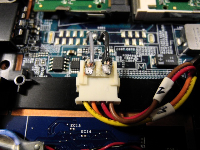
The laptop has mono sound and under the keyboard is a free speaker connector, can I use that to power my keyboard?Attached Files:
-
-
The speaker connections in the Acer 3820TG did not have the same voltage as the USB power connections (300ma v. 500ma). The brightness is considerably less than the USB port, but otherwise it should work. If you ground it properly, you might even be able to turn it off by turning off the sound.
You will need to test the port for power. Use a multimeter and micro probes. It is possible that acer disabled it because the unit has monural sound. -
I don't care about the brightness in this case, if I could do this mod without voiding the warranty.
So, if I understand correctly, one of the 2 pins from the free connector should give me 300ma, but where do I connect the other wire for the ground on the backlit keyboard? From what I understand, it's practically any of the screws under the keyboard? -
If you look at Hendrickson's original modification at the begining of this thread, he used a speaker connection for power. I would look to that for guidance as I have never done it that way.
-
I see that in this image, but it doesn't show where to ground the thing. I think he did it with the cpu fan ground, but my cpu fan connector isn't there. I don't think i have any accesible grounding points.
-
if you want to do this mod without voiding warranty, you have to use a plug that fits into the speaker port and therefore you do not have to search for ground, because the speakerport provides power and ground.
@Bronsky:
You're confusing current and voltage. The speakerport only have 3,5V thats why the LEDs aren't that bright. Nevertheless the current of 300ma should be enough to power on the keyboard backlight. -
Thanks, but, won't the voltage vary with the music played on the laptop?
I tought one of the pins in the connector is a continuous 3.5v and the other one varied with the music. Tomorrow morning I will buy a multimeter and try it. -
you could be right...let us know about your result with measuring the port.
-
I tested the voltage and amperage on the 2 pins. One has 2.3v with 1100mA and the other one has 2.7v with 1700mA. Same thing on the other speaker connector.
So... If I use the 2.7v one, where do I get ground from? -
You should be able to test the ground with a continuinty lead. I would try first in the plug itself to see if you can close the circuit. Any chance of finding a schematic on-line?
And yes, I should have said v not a before. Thanks for the correction. Thats what happens when you type before you think. -
I'm on my way to receive a 4810T backlit keyboard soon, i was thinking about taking near the power cord or so. I've got multimeter so i'll test another way to plug it without taking source power of USB ports, Speakers, or the Bluetooth port (i do not want to weak those i've got working well).
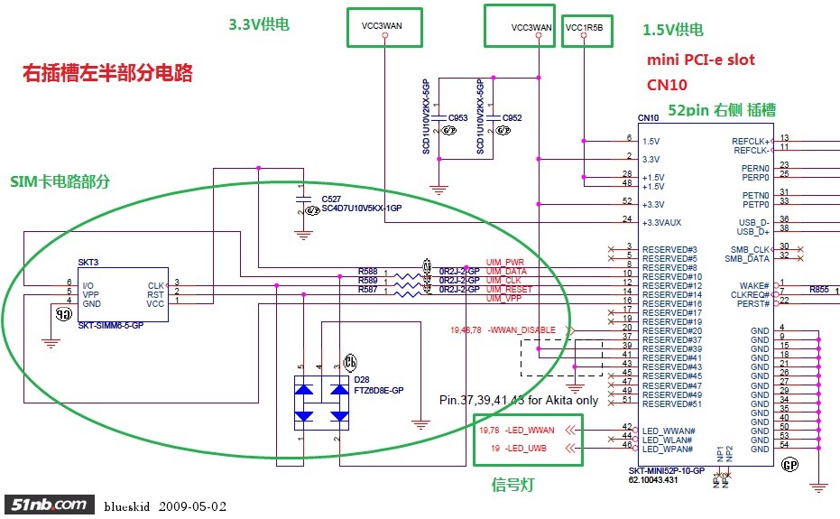
For those not using spare mini pci-e why not sourcing there (3,3 volt)?
I soldered already one for a mini pci-e card, but i still got the second one unsoldered for mini half sized SSD 1,8' free....(just in between the Memory Ram & Synth Pad)
This is the one for mini pci-e 52 pin output (should be not that difficult for 22 pin SSD 1,8' port)
Attached Files:
-
-
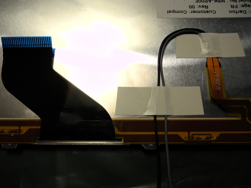
I received today the 48XXT series keyboard backlit. It came directly from UK quite fast.
I'm quite impress by the quality made of this backlit keyboard (Compal). No cheap looking!
The keyboard fits perfect and doesn't looks too thick. Recognized when plugin' in with no probs (i'm with it right now).
It is kind of metallic black paint matte finish and the chicks looks far more responsive and soft-less, much less slippery also. Underneath is glossy black coating.
Missing only the original Bluetooth F3 paint design!!
I do prefer that way.
The original is black matte coating underneath, paint glossy on chicks.
Looks i'll not have to cut anything to fill the place. I'll just have to find the right place to source the power. I think i'm gonna choose 3,3v instead of 5v.
EDIT:
Well, i had to cut slightly the tips to maintain the keyboard, but also had to sculpt the two ones on the side, putted some black paint on one millimeter alloy scrapped.
I'll put images when it'll be totally soldered.
******************
The Sata SSD half-eight spare slot have 22 pin. 7 on the right side for Data, then a coding notch, 15 Pin on the left side with either 3,3v, 5v, 12v...So you can choose which suit better for your needs.Attached Files:
-
-
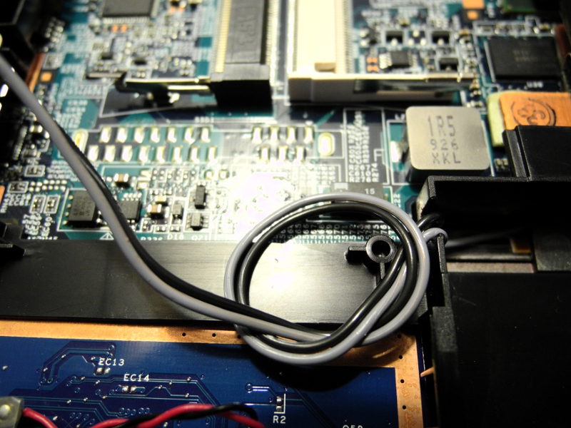
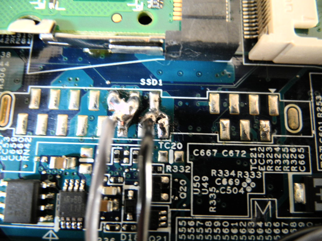
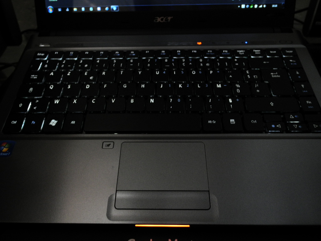
:wink: Here the final result!
As i was telling before, i've got a spare ssd1 slot free (got a 500gb hard drive) and another one i already soldered for mini pci-e ssd nand flash card. So I decided to solder my backlit keyboard on the free ssd1 slot.
This is made directly onto the motherboard. I can easily remove it if i decide to install a ssd (1,8' format).
The previous post showed the schematic order of ssd 15pin (total 22pin - 7 are for Data).
Those 15pin are working by group of three.
-Three are 3,3V and three are GND.
-Three are 5V and Three other GND.
-Three are 12V.
I took the 3,3V because it is enough bright to my need and i can even see it in normal light and this will also save some battery!!
Edit:
Switched to battery for evaluating consumption needs , looks not so bad and i'll say around from 8% to 10% less of battery life.
I don't think i'll a switch On/Off for 3,3V. That would had been the case if i did sourced on 5V.
Enjoy!Attached Files:
-
-
That looks great. Very nice job.
")
-
Thanks!
I could have tell also that i can put a jumper between the wired keyboard to the ssd contacts, so if i have to disassembly again, no need to unsolder. -
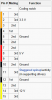
what kind of connector is this ssd1 connector ?? what is the pinout ? -
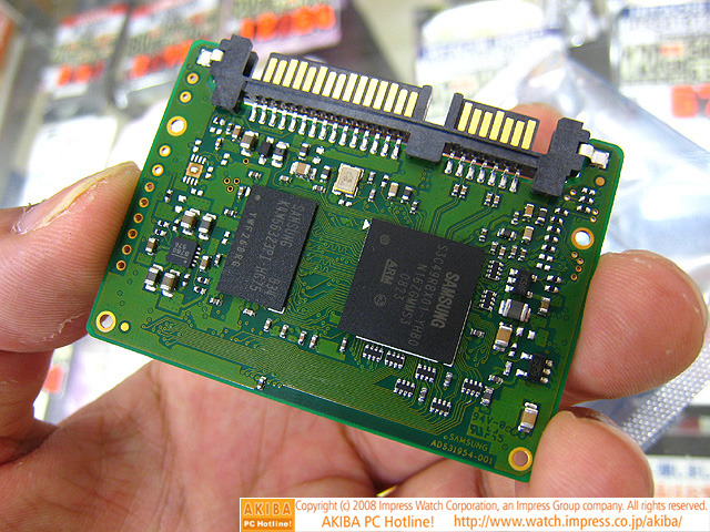
I beleive this Serial ATA connector appear on some of the Timeline 3810T series, shipped with pSSD Half-Slim Cards.
Most of those series were shipped with a 32Gb "Samsung mmcre32gsmpp-mva" (apparently measured 1.18 in. x 0.19 in. x 2 in. - 54mm x 4 mm x 39mm).
Post #575 you can find a part of the pin-out for this 22Pin connector.
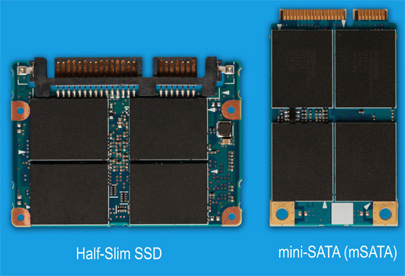
On the attached thumbnails you will have some exemple of Half-Slim SSD Cards and mini pci-e ssd card (refer to post above for pinout).
The man holding the card in is hand have what's was in 3810T serie, the samsung 32GbAttached Files:
-
-
I've added a jumper (it looks big on the shot but it is not), so whenever i will ever disassembly again i can pull-off and remove the keyboard safely.
Attached Files:
-
-
Hi guys! I've been following this thread for a while now and I read quite a bit of it but not everything. Anyway, I've decided to mod my 4820TG with a backlit keyboard as well. I bought the KB from the US but got shipped from Hong Kong. It's made by Compal. Looks good as far as I can tell. I've tested it at work with 5v and it works fine. The dilemma that I'm having now it where to hook it up to. One solution would be to solder it to USB or speaker and put a switch. Problem is that from what I can tell, the kensington port is very small inside for the 4820tg and I don't think I can remove it without destroying the hinge. So that kinda limits the switch option. The other option would be to take power from the bluetooth port. My laptop doesn't have a bt module so I can put it in there. I want to use the actual connector but I can't seem to find a male connector online (mainly because I have no idea what kind of connector it is). I could try to buy a bt module and piggy back the kb on it like it's been done on the 38xx. Can you guys help me out? Thanks.
-
Hope this link will help you recognize the Acer BT 4 pin out.
Add Internal Bluetooth to an Acer
It is for Travelmate series but sure you can recognize some of the components. -
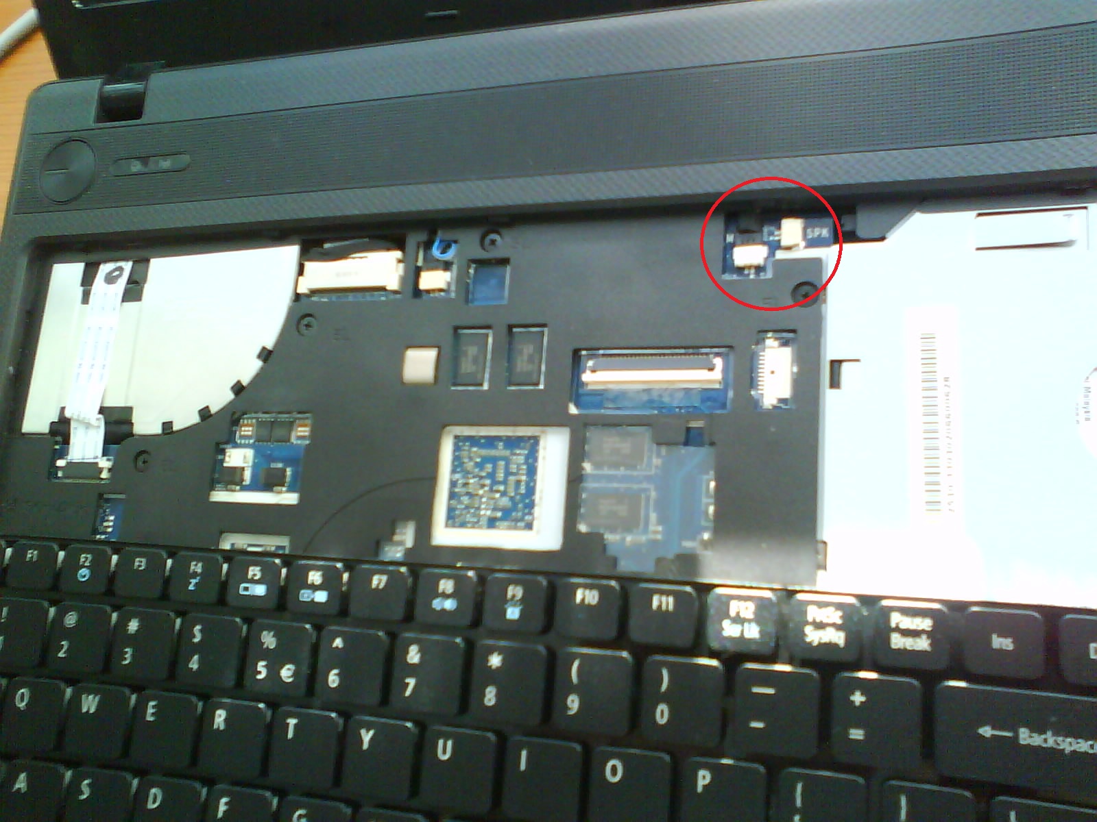
Hi NoMa, thanks for the reply. I thought that nobody follows this thread anymore for a sec there. The link you gave me describes a way to mod the mobo to add BT from what I can tell. I think I wasn't clear enough in my description. My 4820tg has build-in capability for a BT module. As you can see in the picture, the focused connector is where they attach the BT module on variants that have it, and then they screw it in the metal pin lower. So I was thinking about buying a BT module that's usually put in the 4820t (i think it's the BCM 92046) and then piggy back the kb power to it, like you did for yours.
http://cneacsu.files.wordpress.com/2012/05/img_0064.jpg -
Hi elfwrath, i think it's the BRM 2046 BT Module that fits into your 4820TG. The BCM 92046 is for pcie slot?
Take a look in the Acer Aspire 4820T Service Guide on page 141:
http://support.acer.com/acerpanam/Manuals/acer/2010/ServiceGuides/SG_AS4820T_20100525.pdf
BT module can be found on ebay f.e.:
BH.21100.004 Acer Ao531H-1077 Bluetooth Module Brm Foxconn | eBay
or
ACER Foxconn Bluetooth Daughter Card Module FOX BRM 2046 BT 2.1 T60H928.33 BT06 | eBay
But make sure that the BT cable is included!
Nevertheless, you should consider the fact, that the BT module only provides 3,3V which isn't as bright as 5V from a USB port. -
I thought there was a discussion of the BT modification further back in this thread, but Maikvalberg has it right. If you buy the module, you might be able to resell it on ebay and keep the cable, which is really what you need. Then, just take power and ground off the fitting and wire it to the KB. I think this is the least invasive method for making a backlit KB on the Acer. I took power from the USB port but would serioiusly have to consider this if I was doing it today. Good luck. And, it takes some time, but we do read this thread when it comes up.
-
I've actually ordered one just like those and got it today. Now all I need is to figure out which pins to use for the power leads, as I'm not sure which is which. Regarding the voltage, I understand that it's only 3.3v but that's the only (easy) way to have a switch to turn the backlighting on/off. Since there's not enough room in the kensington port to put a switch that I can plug to one of the usb ports, it remains the only viable option. Plus, if after all of this I'm not satisfied with the intensity of the light, I can always try to get a higher voltage later on. Anyone know which pins are the power ones on the mobo connector?
http://cneacsu.files.wordpress.com/2012/05/img_0067.jpg -
I would measure the pins with a multimeter. But there is one thing i'm not sure about: Does the launch manager work, without proper installed bluetooth module?
-
Unfortunately I don't have easy access to a multimeter, so that's probably gonna take a while. Also, doesn't that mean that I need to power the laptop while it's open to get a reading on the multimeter? If that's the case, I'm not that comfortable with that, as I can mess something up quite easily. I'm not sure about the launch manager, but I guess it should work if it has a BT module installed as it should be the same software that's used for variants with BT installed from factory.
@Bronsky: I don't mind keeping the BT module as well, as I can use it for my phone and such. -
If you can find a spec sheet for the module, it should tell you what the pins are so you won't have to wait for a multimeter. That is a damn good question about the launch manager. Since it has been done, there must be a way.
-
Just bought a schematic file for the whole laptop. Should be useful in the future as well. It looks to be right, as the connector type seems to be the same as the one on the laptop (CN9). It appears that the power to the BT module comes from pin 5 and the ground is pin 4. Or is it 2 and 3? Man, I'm rubbish at electronics...
http://cneacsu.files.wordpress.com/2012/05/16-05-2012-20-14-45.png -
You bought the complete schematic? Where do i get those schematics? I'm reaaaaaaally interested in a schematic of the 3820TG!
In my opinion pin 5 and 4 should be right.
If you install the BT module there should be no problems with the launch manager, but where do you get power and ground for the keyboard then? Either you mod the BT cable, or you solder on the BT module.
If you just use the BT cable to connect the keyboard, then you have to test if the launch manager works, but i guess it works, because the mosfet Q15 controls whether current flows or not and it has nothing to do with the BT module. -
I bought the schematic here: Motherboard schematic & Block Diagrams, Laptop / Notebook Schematics For Repair . There seem to be a few websites like this so you should be able to find one relatively easy. Regarding the power pins, I initially thought the same but it appears that the convention when it comes to the power for the other connectors suggests it should be pins 2 and 3, because they have the USB port number and + and - . I'm going to ask the electronics guy at work about it. When it comes to actually plugging the wires, I'm thinking about shoving them in the connector next to the required ones, as there seems to be some space in there and would be preferable to soldering or stripping them.
-
If the right pins were 2+3, that would surprise me. Usually pin 2+3 are the pins for data transfer...correct me if i am wrong.
I'm interested in the effect on battery life, please tell me, if you are successfull with your mod. -
I just talked to the electronics guy at work and he thinks it's 5 (+) and 4(-) too, so I'm going to use those. Btw, just to confirm: the keyboard pins are 1 (+) and 4 (-) right? Now all I need is the FFC connectors I ordered and I should be good to put everything together. That's probably gonna happen in the next few days/weekend. I'll let you know how it goes. Hope for the best
-
you are right with the keyboard pins. good luck
-
Best of luck. Let us know how it turns out and take lots of pictures.
-
Hey guys, just to give you an update. This thing is a hell of a lot harder than I originally imagined. Getting a piggy back on the BT connector is harder than finding a needle in a haystack. I've managed to test the BT module, it works fine and the launch manager works perfect, but actually being able to connect the KB power wires to the connector is friggin' hard. I'm rapidly getting frustrated and I think I'm going to wait until the weekend as I hate having to take my laptop apart every single day. I'll let you know how it goes when I get some tangible progress. Oh, and you guys were right: you need to be a Jedi Master with the soldering iron to make this work...
-
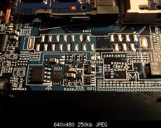
Whats about the idea to solder the KB power wires directly to the points on the right, which marked as LED1 on the BT module:
I've measured the power consumption of the KB at 3,1V. It's only about 6-10mA.
@5V it's ~ 60mA
So maybe there is someone who can measure the LED1 points for you if you don't own a multimeter.
If all else fails, you have to take your BT module and find a "Jedi Master" who solder wires directly to the connector J1.
-
Those soldering points at LED1 look interesting. If they are designed to power an indicator light, it could be a decent place to take-off power and ground. They would be a hell of a lot easier to solder than the pins on the connector. Make sure to use plenty of flux.
Acer TimelineX 3820TG Backlit keyboard mod
Discussion in 'Acer' started by Hendrickson, Jun 12, 2010.