Hey Guys,
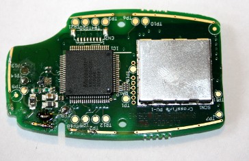
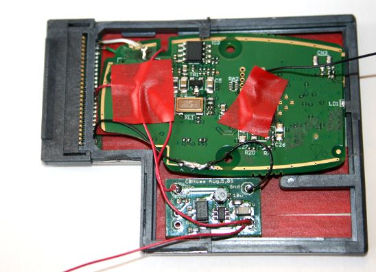
I did a bit more of testing while waiting for the other components. I created a better version of the prototype where I get rid of the internal pcb. Then I played around with the xbox receiver pcb (read: totally raped)and I somehow managed to squeeze in the xbox receiver into the expresscard. Im still amazed that the xbox receiver still works after what I have done to it.
The only thing left is the voltage converter (I gave up on inserting the mouse receiver there as well). If I can squeeze in the voltage converter into the expresscard slot, then this will 100% work.
-
Well I have done some reading, and I think I will most likely go a route like what Wattos is working on.
It looks like the needed data connections are present in the ExpressCard connection for a typical USB 2.0 connection. The main concern being the power is 3.3V and not the needed 5V. If you use the expresscard connection to send the data, you can run 2 wires to any USB port to be soldered on the back to grab the +5V and GND. This would be a paralell connection and since does not include the data, would not tie up any USB ports on the machine")
My main obstacle now is finding a pin diagram for expresscard It seems this is locked down pretty hard (and you allegedly have to pay $2500 to get a compliance/partner package with such info)
If I can find this pin diagram, I will definitely make a expresscard insert. I may even work in an addition plug system so that it is fully removeable without any wires showing and without rendering the expresscard slot useless to any other devices.
this site may help with the pinout stuff -
Be careful of running parallel... I have heard that hooking up two powered USB ports can burn out one or both of the ports. If I run across the thread again, I will link it.
-
as long as the 2 devices running off the us port are drawing less than 500mA should be safe
considering I am talking about an xbox receiver and a wireless mouse receiver at most, I should be ok. I do not use any other powered USB devices except for a thumb drive.
And I am talking about powering 2 devices off one port, not one device off 2 ports -
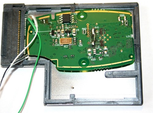
yes you are correct. This is what I have said from the beginngin ^_^. Also, as you can see, I already have been able to connect the logitech receiver over the expressport. It worked fine under 3.3v.
As to the problem of 3.3V instead of 5V, I actually will be using this, which will do the trick (its in transit and I cant wait for it to arrive), should fit into the remaining space and will not require any additional wires to any USB port. (it also provides enough current)
Also, your idea with power is sound. As a matter of fact, you probably only need to grab 5+V as its very likely that GND is the same everywhere (would have to verify that with a voltage meter), and the expresscard pins have more than enough GND connectors. This is what non-powered usb hubs actually do, they connect all the "child" ports in parallel. But you will be handicapping that particular port to handle less devices. If devices want to suck more power, you will get a voltage drop, nothing should happen to your hardware, otherwise non-powered usb hubs would be breaking laptops and desktops
oh, and yes I have verified that the first table on the page is indeed correct with respect to the USB pins. -
Looks like we are about on the same page then
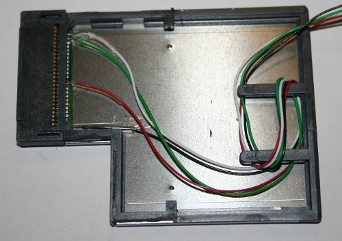
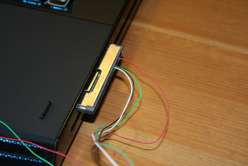
I looked at that power supply and think I would prefer that over my idea, keeps me from having to actually solder anything to the motherboard. What was the expresscard you are using? Looks like a CAC reader. And in your last set of pictures, what are the random wires coming out of the slot for? Were those just to test the logitech part? -
The random wires were to test if the logitech mouse receiver works, to verify that I have the correct pins and that it works ^^. They will not be there once Im done ^^.
Also, you can get any card, as I am only using the connector anyways. A nice thing on here is that the remaning part of the pcb is grounding the enable USB (which means the card uses USB). I use this card is because it was the cheapest I can find, its called OmniKey Cardman 4321 -
Yikes, starts at $47 is what I am seeing online. I think I may try something like this. I could also position the button so that it is just on the outside edge, easily accessible when the card is inserted in the laptop.
-
yes, the button position is not a problem, but I think we will need to have a smaller button, as this might be too fat.
The card you provided seems to look good, but, looking at the picture i worry that it might not provide access to all pins, (especially the usb pins). That would however seem very weird as the card should only act as a usb hub..... -
Wow you guys are doing an amazing job!!! keep it up. Very kewl
-
Any update on this Wattos?
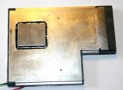
Just ordered a smart card reader and the power board myself. Have you confirmed that your receiver still works after the dremeling? I saw that you cut a trace at the top of the board but am not sure it that was just a test point, looks like it came off the ground plane. -
hey,
I did test after dremelling and it did work. Otherwise I wouldnt have posted it. Unfortunately I wont be home this week so I will not be able to continue on this.
-
You could use a DC to DC Boost converter to step up the 3.3V -> 5V, Seeing as its not a temendious amount of current being used the footprint of the booster shouldn't be a problem, Thats the route i was planning to take anyway.
I'm interested in having it all Expresscard Mounted as it would be a nice accessory tbh
Edit - For example this, http://www.sparkfun.com/commerce/product_info.php?products_id=8999
Higher current ones are available as i believe the one above is only rated to 100mA. -
Step ahead of your Deathcore
http://www.circuitsathome.com/products-page/power-supplies
The model you linked supplies very little current, that could be an issue. This design goes upto 600 mA (more than the USB spec even calls for) -
yes, and also, the xbox wireless receiver sucks 200+ mA so the one linked wont do
-
The design scook9 linked would do the job, as it's rated for over the USBs rated maximum current anyway, The one i linked i'd used before :3, Scook's could easily be encased judging from the images you posted.
-
I actually got that link from Wattos lol
But yes, it should work in both space and electrical requirements -
/me is getting excited and wants to go do some shopping now.
-
Ya I went ahead and ordered my expresscard and power board yesterday. Been sitting on my hands long enough about this project
Should have some results pretty quickly after all my parts get in.
To summarize so far, my goal is to pretty much take the USB design, and make it into an ExpressCard design. It will be completely self contained and useable in any laptop that has an ExpressCard54 slot -
Same as what i plan to do, Update us with any progress, I intend to do the same when i get round to ordering my bits and bobs.
I've been wanting another project for a while. -
to summarise so far, you goal is to steal my idea
-
don't fight kids, we could all benefit from your discoveries
-
lol, I wasnt being serious.
-
No, I am stealing it. Was better than my idea
Now it is a contest of who can do it prettier! -
lol.. This is great.. I cant wait to see how this works out..
-
so, I am almost done. This thing I have now works in my PCI Expresscard slot, my controller connects to it and works correctly. The only thing which is left is to order a dummy expresscard (anyone know a good place?) and use that "backplate" to install a button to it and glue it to my pci express card.
Attached Files:
-
-
Nice!
it looks awesome man!
just didn't get how are you going to expose that button since the thing is stuck inside the express card slot.. -
I detached the old button, bought a 5 mm one and will use 2 wires to connect it to the new location of the smaller button
-
i hope u plan to make a thorough tutorial after you finish, this thing is brilliant!
-
Looks good, I have all my parts in finally and will be putting it all together this coming weekend. School has been hell and is keeping me very busy
-
do you have a 5mm push button?
the button from the receiver is too big to be mounted on the side of the expresscard -
I was going to try to reuse the current button. If not my friend has a lot of spare parts and we will be doing the work at his house so we will see what he has around
-
hi - just looked at your images for the dremmeled out receiver - are the copper contacts actually used for anything at all? it doesn't look like it from your images. if that's teh case, then i can dremmel mine down to fit in the wwan space in an m11x.
-
which copper contacts? Do you mean the ones on the outside? They are just easy access to ground.
-
You'll still want access to the "connect" button, don't forget about that. Burying this deep in the laptop isn't such a great idea unless you can route the button somewhere accessible.
-
i read about that deeper in this topic - however, the only time i've ever used the connect button was when i got a new controller - and if the mod works right (i.e. i hope it won't reset itself everytime i turn it off *cough*ps3controllerviamotioninjoy*) i would have no qualms about unscrewing the bottom of the laptop and pressing the button.
thankfully the screws for the m11x are retained in the bottom plate, so they won't even fall out and get lost either. however, if push comes to shove, i could try ebay for a replacement bottom plate and drill a hole in that.
right now, i'm just looking for a mini pcie card. -
The problem is that you need to be powered on while pressing the button. You should be able to route the button to the keningston lock if you are not using it. You would require 2 wires
-
Is there a guide to take the receiver apart? or you just have to break the casing?
-
Take a look at this youtube video. The first 2 minutres show how to get to the receiver without totally destroying the plastic cover
-
Once again, thanks Wattos
-
Yeah, thought that too in my mind but neglected to mention it in my post.
-
Taking apart the plastic housing was pretty easy, just popping the glue sucked. The hard part for me was the giant plastic plug on the cable going into it, that thing was unnecessarily large
-
the cable was where i started prying from - once that was suitably deformed, the rest popped up.
it really boggles my mind as to why microsoft decided to make the cable so darn long. it's not like having a usb stick dongle would have affected range much, if at all, anyway. -
M$ probably aimed for desktop machines in general. The dongle would have been probably twice as expensive if it was smaller. And it would be a pain in the but to press the button if the receiver was in the back.
But, be happy, at least you have some exciting stuff to do on weekends! -
Even not changing the form factor of the PCB they could have made it simply a dongle and saved on wire costs and a slightly smaller housing. Just poorly thought out on their end, but at least they offered this solution at all.
-
well, I have been testing my expresscard receiver, and its just as I thought initially but never posted. That long usb cable most likely serves as an antenna. Right now I have a very bad range (only 1-2 meters). This might also be because its inside the laptop now
-
Ouch. I'd only be sitting about that far from it myself, but that's not great. Also kind of makes sense with the cable doubling as an antenna. I was thinking of shortening my wire to only be a few inches and make the adapter closer to a dongle. Maybe that would be a good test of that theory. I'll drop a line after I've tried it, as it seems to be a good interim solution for me anyway.
-
I did notice that there seemed to be an extra cable for it being just USB on that plug....interesting thought
-
just found the absolute perfect thing for an internal 360 wireless receiver.
dirt cheap, too (in comparison to other solutions) - and lots of empty space, so i can see myself making the adapter fitting into the space very neatly
The Adapter
![[IMG]](images/storyImages/ux_a09040100ux0268_ux_n.jpg)
buying one now. judging by the connectors i can hopefully plug it straight into the usb connector on the wireless adapter itself. -
Let us know how that goes!
[GUIDE] Installing an XBOX 360 wireless controller receiver into the M17x
Discussion in 'Alienware 17 and M17x' started by cookinwitdiesel, Mar 29, 2010.