
Useful Information:
Schematic of M15x mainboard
http://notebookschematic.org/data/NOTEBOOK/attachments/SC/products_files/Dell Alienware M15X_DELL_FLEX_Defiant_RevA00.pdf
A repair of the mainboard
http://computer911.byethost10.com/example/e01.html
My own story:
In december 2016, I burnt my voltage regulating circuit on the motherboard, and without enough documentation, I couldnt repair it. Thats why I decided to create this thread - so that we can gather info and possible modifications and repairs.
I bought a replacement motherboard that is somewhat different in the voltage regulating section and would like your thoughts on this.
This is how the old board looked, after taking it out:
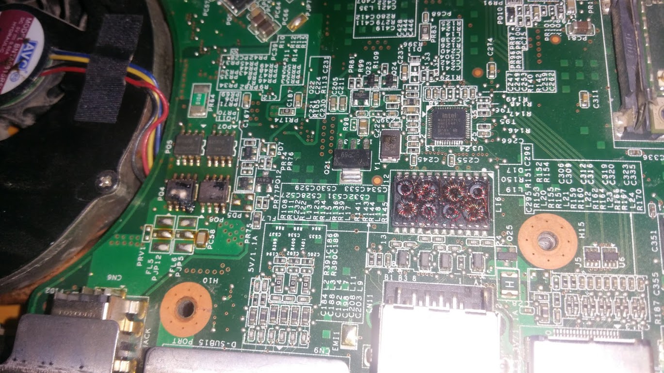
Yup, it had been quite hot!
Then I recieved the new board and noticed some differences (new board below old)
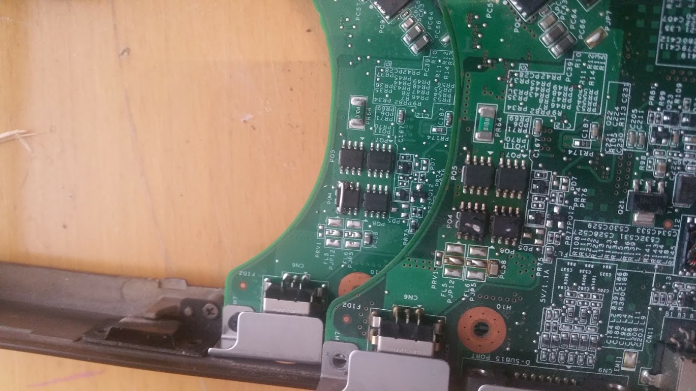
If you look carefully, you will see some solder had melted and short-circuited something. On the new board, theres also a jumper, bypassing one of the power regulators ( I presume it is). Is this some fuse function? Perhaps to limit power draw?
-
Image links arent working...
-
Great idea on this thread but your pics are not loading.
@maxslo. Do you know where we can get a schematic for the motherboard? Found one for the older area-51 model but can't find anything for the 2009 model. -
Maybe this:
![[IMG]](images/storyImages/115041-ca2a0b713cb733fdcfdb4e84f3b338cd.jpg)
-
Do images work now?
-
There should be a schematic for the M15x somewhere, i know I've seen it before (For the Dell M15x model), looks like OP found it
")
The schematic picture works, but not the ones in first post... -
Uploaded pictures.
-
You are correct; they've 'fixed' this board by bypassing this particular power mosfet entirely.
It is basically a heavy-duty switch and some design flaw has caused the trigger to fail. Rather than fixing the problem at the source and manufacturing revised models of the same motherboard they've instead opted for white-washing the problem on the existing stock of the first production run. The result being that these board will no longer burn up, but power consumption will be higher since (part of) the power to the receiving component (the dGPU, for example) can no longer be switched off. Battery life and thermals should be worse on this band-aid board compared to the original, unmodified sample.
Probably the issue is with the switching signal (embedded deep withing the pcb), rather than the specifications of the power mosfet itself, otherwise a higher rated component would make an infinitely better fix. Hmm ... well ... or rather; no, because soldering a $0.01 wire + $2.00 time is cheaper than a $1.50 chip + $4.00 time . If you'd want to diy a better solution then pen down the original's part nr. (scribbles on the chip itself) and find a substitute with better specifications. The silly bypass can then be done away with.
-
Wow, never even noticed this and I have 3 different M15X boards and one new one on the way. Good find.
-
there's any way to turn on this notebook without power button ?
-
Sure; short the power-on and a ground on the power button board's connector on the motherboard. The power-on sequence works like a relay; small signal turning on the rest of the power circuits in a cascade. It is also 'once-on' -> 'remain on', so for forcibly shutting down you'd have use the same method, except keeping the short for several seconds, which does the same thing as pushing down the power button for a while.
It is best to use the schematics, rather than trying random pins, and fortunately MZWiZard has managed to find these:
![[IMG]](images/storyImages/2hev5mg.jpg)
![[IMG]](images/storyImages/2s76tth.png)
Only tricky part is that you need to know which pin is pin#1. There should be a number labeled on the mb on one of the connector's corners or it might have an arrow or square indicating #1. Mind that this connector is using 2x 10 pins, one 10-pin row at the bottom and another at the top (thus the flat-ribbon cable is also double-sided).
If there's no label then there's only two possible combinations; bridge the fourth pin from one end to the fourth pin from the opposite end (#8 to #14) and the same for the opposite side of the connector (#7 and #13). There's no harm in shorting the wrong combination, so you're good to try both.MZWiZard likes this. -
A small update: I just tried to up the voltage on the GPU again and run a delimited PSU. Drawing almost 220W max, the M15x doesnt get hot where it did with the old board - in the top left beside the keyboard. A couple of hours of gaming FC3 following GTA V gave NO throttling or heat-up spots - and the old board would have done both. Could it be, that the jumper wire across the voltage regulator actually lessens the strain on the motherboard?
-
A little, yes. But it is hard to fathom that it'd make a noticeable difference.
More likely is that your old board had incrementingly failing components before the catastrophic meltdown. Especially with these power components having multiple identical ics that means one or more can fail and the system would still run, yet putting more strain on their still-working brethren. Much like continuously downsizing departments, eh?MZWiZard likes this.
M15x mainboard info / hardmodding /repair
Discussion in 'Alienware M15x' started by MZWiZard, Feb 19, 2017.


