So here goes the details of my backlight keyboard implementation.
It is a method where the ON/OFF touch sensor switch is hidden from the naked eye.
Here is a Youtube video of the hidden backlight ON/OFF touch sensor working as desired:
YouTube - N71JQ backlight Keyboard implementation‎
The schematic is attached to the end of this post.
Let’s start with the material that I used for this project:
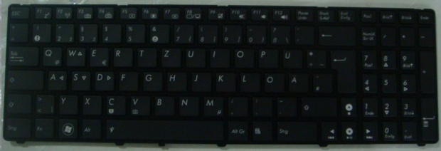
- A backlit German Keyboard from here: Asuspart.eu
- A 470KOhm resistor with package size 0805
- A 10nF capacitor with package size 0605
- A QT118H sensor chip with package size SOIC from: QUANTUM ATMEL|QT118HA-ISG|SENSOR| Farnell United Kingdom
- A FDV303N Digital FET with package size SOT-23 from here: FAIRCHILD SEMICONDUCTOR|FDV303N|DIGITAL MOSFET| Farnell United Kingdom
- A SMD PCB test adapter board from here: ROTH ELEKTRONIK| ADAPTOR, SMD, SO-8, 1.27MM | Farnell United Kingdom
- Male/Female connector sockets to connect the wires from the keyboard backlight to the wires coming from QT chip like these ones: HARWIN|SOCKET, VERTICAL, 1ROW, 3WAY | Farnell United Kingdom and SAMTEC|HEADER, 2MM, SINGLE THRU HOLE | Farnell United Kingdom
- Conductive Wire Glue (optional) similar to this: Wire Glue
- Some Heat Shrinks (optional). One can also use a tape.
- Double sided tape
- Soldering station
- Some thin aluminum or copper plate for sensor pad
Note the links above are from UK Farnell. I ordered all the stuff from their partner shop in Germany here: http://www.hbe-shop.de/katalog/
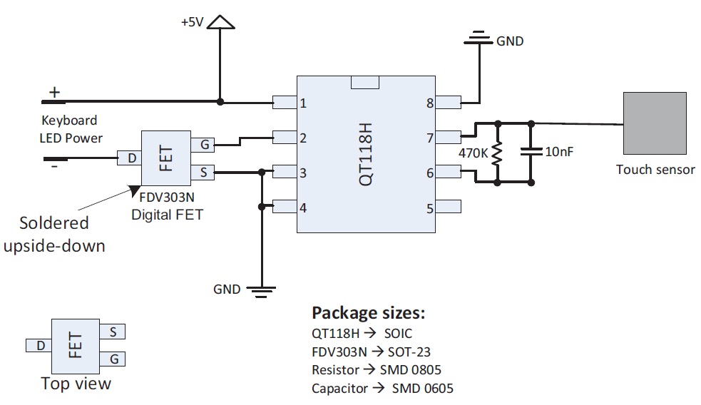
Similar solutions implemented on different notebooks exist already in this forum. The difference here is that the QT118H chip is not directly powering the keyboard backlight. It is powered here through a MOSFET. The MOSFET is on the negative terminal of the keyboard backlight supply.
The QT118H is specified to sink maximum of 2mA and source a maximum of 1mA. If no MOSFET is used then QT118H has to sink 200mA. So in the other implementations not using the MOSFET, the QT chip is forced to sink a much higher current than it is supposed to. It can overheat and get damaged.
I used QT118H instead of QT110. The reason is that the QT110 was not available here in Germany. There are some differences with respect to the operation. QT110 is active low and QT118H is active high, but in the toggle operation mode the difference is not much. So the same method should also work with QT110.
Furthermore, looking at the data sheet of the QT chip one can see that it is specified to operate as a sensor which can be implemented behind different materials like plastic and glass. The metal touch plate does not need to be touched directly.
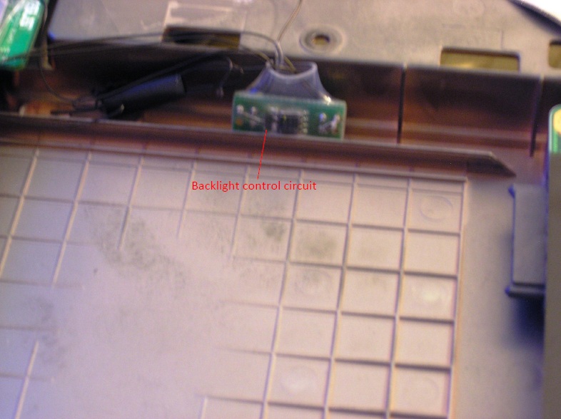
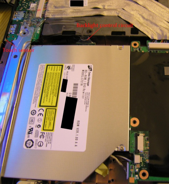
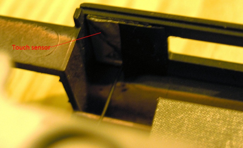
On the N71JQ, on the right side there is a plastic cap covering the hole for an optional TV card antenna. This is located between the blue-ray drive and the USB2.0 port. I attached the touch sensor behind this plate using a double sided tap. So touching this small round plastic piece turns the keyboard lights ON/OFF. The touch sensor itself is made of a square piece of aluminum plate to whom the sensor wire from the QT118H chip is soldered.
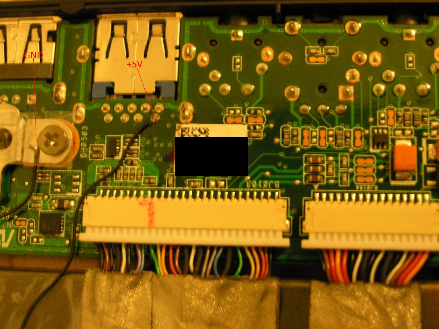
The power for the touch sensor circuit is taken from the +5V supply pin of USB3.0 port .
Other members in this board has used the wire glue in order to glue the cable to a +5V source on the mainboard. I tried this also, but it was not a reliable solution. It is not that easy to get a good connection by gluing the wire to the power pin using this conductive wire glue. The resistance of the wire glue seems to be high. It caused some voltage drop at the connection point and this contact point was getting warm. After some days of use, the sensor became less sensitive as the connection became little bit loose and the QT118H was receiving less than 5V. The touch sensor was not responding very well anymore.
Finally, I removed the wire glue and I soldered the supply wire coming from QT118H directly to the +5V supply pin of USB3.0 port. Since then the circuit works perfectly.
Note: The soldering method requires lot of care so that a very tiny bit of solder should be used otherwise you can lose the warranty, because it would be easy for ASUS repair center to see that you have soldered something there. I did it under a microscope. Besides I have the necessary tools to remove the extra solder if I need to send the notebook back for some repair in the future.
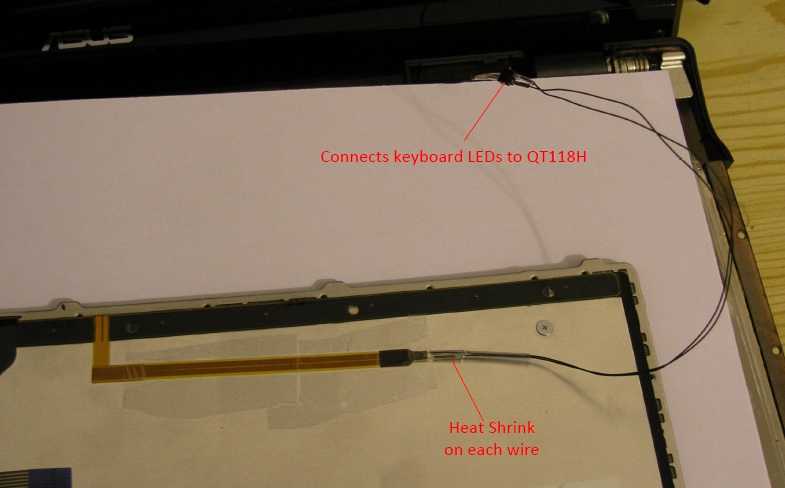
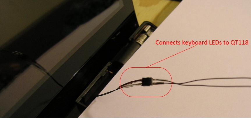
The power cables coming from the QT118H to the keyboard backlight are connected through a socket. This makes it easy to disconnect the keyboard from the notebook. No need to cut the wires if for some reason one needs to remove the keyboard.
As shown on the schematic, I connected a 470KOhm resistor in parallel to the 10nF as suggested in the data sheet.
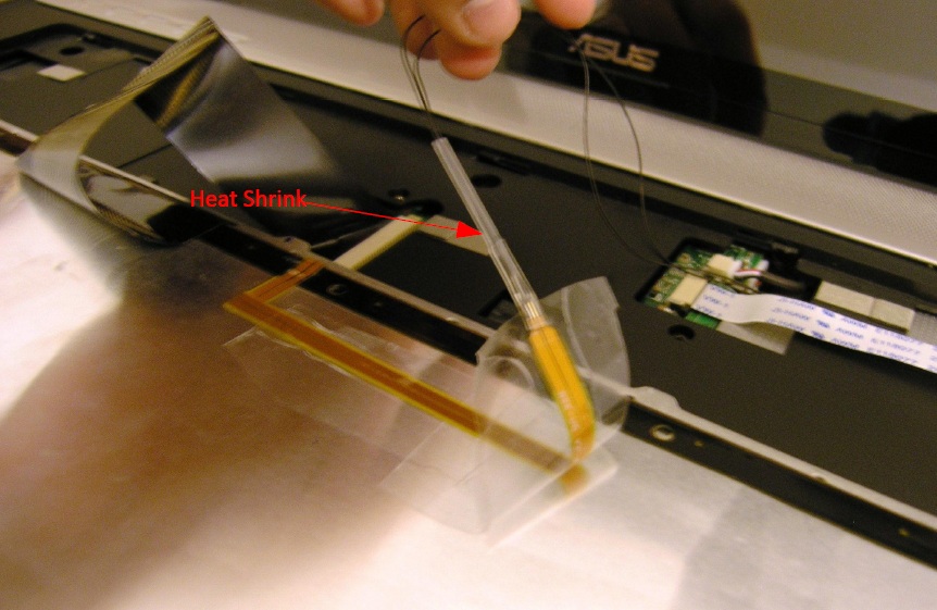
For isolation purposes I used heat shrinks in many different places. Different sizes of heat shrink tubes are required. If that is not available one can also use some normal tape.
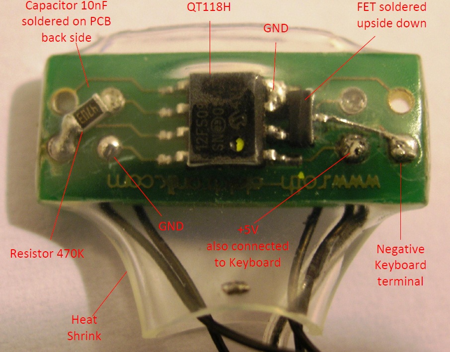
Below is the schematic and the photo of the implemented circuit.
The circuit is soldered onto a general purpose 8 pin SMD PCB adapter board.
The MOSFET is soldered upside-down because of the gate and source terminal places need to be switched.
On the PCB the original trace coming from pin 2 and which goes to negative terminal of keyboard backlight is cut. Then a MOSFET is soldered between pin 2 and the negative terminal of the keyboard LEDs power connector.
-
Attached Files:
-
-
Warning: If somebody want to implement the solution I provided here, please do it on your own risk. I am not responsible for any damage that you do to your system when implementing such a solution or even if you burn your fingers while soldering.
The N71Jq disassembly guide: http://www.gentechpc.com/Asus/N71VN Series Chapter 02-v1.0.pdf
A new link to the guide: http://hotfile.com/dl/84397985/b319264/Disassemble_N71VN_Series_Chapter_02-v1_0.pdf.html
The N61JQ disassembly guide: http://www.gentechpc.com/Asus/N61JQ/N61VN Series Chapter 02-v1.0.pdf
Thanks to Ken Lee from Gentech PC for providing the links to these guides.
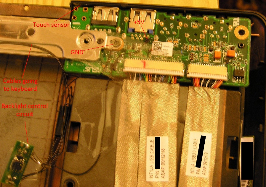
As shown in the pictures, the cable coming from the keyboard backlight is connected to a socket connector which makes it easy to remove the keyboard.
The two power cables from the keyboard are guided over the metal arm.
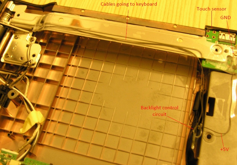
The QT118H circuit can be placed in the empty space near to the CD drive.Attached Files:
-
-
Sorry, some of the pictures are not that clear.
I took the shots at night.
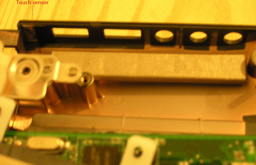
The pictures show the power supply and ground connection as well as the hidden touch sensor.
The GND (ground) wire is not soldered. It is screwed to the metal arm which is contacting the ground on the USB/Audio board.
The +5V supply for the keyboard backlight is soldered to the supply pin of the USB3.0 port.
The touch sensor plate is placed near to the USB 2.0 port with a double sided tape. Some black tape is covering a side of the aluminum sensor plate.
This is to avoid it from contacting the external metal body of the USB port which is usually connected to ground.Attached Files:
-
-
Hey Turbo,
Absolutely freakin' GREAT job! It's like the big professional brother of its (my) DIY retarded little brother
Now I see why I didn't got the full 5V's. I guess I'll start using the backlight only when I need it to save the chip.
Is your touch sensor just as responsive when your feed are touching the ground as when they are not? That was one of the things I noticed happening with my retarded brother version. -
Thanks PaulW.
It works great, but it's a pitty that I did not get the time to implement it when I needed it the most.
I needed it in June where I was writing my dissertation on the notebook every night until 2:00.
I am not sure how the sensor pad will behave if it is touching the ground. I never allowed it to touch the GND of the system.
As mentioned before, what I noticed was that the sensor behaves erratically when the +5V was not soldered directly but was rather attached with wire glue.
Sometimes it used to work right away and other times I need to touch the sensor multiple times.
I did not experience that after I removed the wire glue. -
Lol I ment feeT instead of feeD, and ground as in the actual floor.
Indeed it might be the wire glue messing about. -
You were asking about feet and I was thinking you were asking about the touch sensor touching GND.
After I soldered the +5V, it seems the circuit is very resposive now.
I tried it with lifting my feet of the ground of course when sitting on a chair and the sensor reponsiveness did not change.
I also put my hands off the table where the notebook is sitting when I touched the sensor and the sensor was still working fine. -
Great work, Turbogear!! Well done, looks really cool
-
Thanks.
Let's see if somebody from the N61JQ community will also implement a similar solution.
-
Yeah.....................................
-
In case somebody from N61JQ group is interested in implementing it I will be happy to help if I can.
-
I added two more photos showing the front and backside of the backlit keyboard.
-
Could you give me a link to the touch sensor? I would like to do some more research and attempt this on my UL50VT.
-
Do you mean the schematics?
The chip that I used to build the touch sensor is QT118H and the schematic is attached to the bottom of the first post in this thread. -
I found this nice guide which is posted by Ken Lee from Gentech PC and it shows how to change the color of the backlight.
The keyboard looks really cool with this color mode.
This guide is a collection of information posted by Ken in the following thread: http://forum.notebookreview.com/asus/515430-asus-g73jw-discussion-thread-20.html#post6710457
Thanks you very much Ken for this guide.
Last edited by a moderator: May 6, 2015 -
isnt there any photos for your N71JQ with the backlit keyboard light on ?
-
I did not take photos but I have a video that shows the backlights on. It is in the first post in this thread.
-
Just a quick question..
Would taking the power from the USB 3.0 port make it unusable or anything..
If so what would happen, and would wire glue suffice as opposed to soldering..
And if i used wire glue would this void my warranty?
Oh and any reccomendations for backlight colour if i can be bothered modding it
Thanks
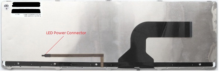
EDIT: I was reading the disassembly guide just then (out of boredom) and found that the N61 has an "LED Connector" so it is possible to just hook up the backlit Keyboard to that rather then have it run off the USB power.. I have no idea wheter as to if it turns off or what. It does however fix my problem and save voiding the warranty
I shall test this myself! I can't wait now
I took a photo for people to make sure/know what to look for, hopefully the quality is good enough
-
Yes wire glue could be removed with a small sharp pin so it should not leave any traces.
I also tried wire glue before, but the connection was not that good.
That's why then I went for soldering, but my soldering skills are quite good so in my case the soldering will also not leave any traces.
There is a connector for the backlight keyboard on my N71JQ also but it is not functional.
I remember Ken Lee tested this connector on N61JQ and he said that it was not working there also.
With respect to power draw, the keyboard backlight needs around 140mA of current (0.7W) and the USB3.0 port according to the specifications should be able to provide 950mA (4.75W).
I already have used devices like 2.5" Hard disk on USB3.0 port together with keyboard backlight, but I did not experience the case where the HDD was having problems due to too less power. Maybe in the future if I have a device that is needing larger amount of current then the keyboard light may not work together with the external device.
With respect to backlight color, my personal favorite will be blue. I have implemented the dark blue color foil, but later removed it as the amount of light coming from keyboard was reduced. In the future I will use a light blue foil that would be more transparent so that more light will go through.
Good luck with moding and if you need any help just ask me.
-
Thanks for everything!
I have a friend that's an awesome solderer and he shall do it for me!
I have just one problem, on ebay i cannot find a GT118H or a QT110H...
Tomorrow or even today i might go check if they stock it locally, doubt it however... And everything else on ebay is in bulk...
That's the only current problem atm.. lol
Thanks once again!
EDIT: Scrapping sensor/SMD it's just a tad too much...
I'm just going to have it on whenever my laptop is, seeing as that will be alright for me now that ive confirmed that the USB port is fully functional afterwards. Will get pics when it's done etc to show how it looks/the difference inside a N61 vs a N71..
Hoping for this to work 'cos it's gonna look sexy!
Btw anyone had any problems of the Keyboard touching the screen?
BTW, that's just normal celophone yes? Ive got some blue stuff from school for free but a friend is offering heat proof stuff.. i don't know whether to take it or not... -
Here in Europe I have ordered them from Farnell.
It seems like this chip is not being produced anymore.
It could be the reason you don't find it that often any more.
It looks like that Atmel has replaced it with a new chip. Here: Atmel Products - Buttons, Sliders & Wheels - Devices
If QT chip cannot be found then one may have to redesign the circuit using the new chip from Atmel. -
hey turbogear, how come the link to the n71jq disassembly doesnt work anymore?
-
Just wanted to say, ive got ALL the parts i need. I shall do a similar thread to you Turbogear! It was mainly inspired by you so yeah
I'm waiting a while before i actually solder it down, due to new thermal paste..
I however will report how it goes as i said, have fun modding guys!
-
Yes, it seems that link is not working anymore. This link was provided by Gentech PC.
I have this guide, but at the moment I am not sure where I can upload it to.
The Notebookreview allows maximum 500KB and the guide is 3.5MB.
Any suggestions for the server?
Good luck with modding.
Yes a thread for the N61JQ keyboard backlight mode could be useful for the others.
-
You could try somewhere like megaupload.. or maybe someone has a FTP or something?
I have the N61 guide too, if you wanted that!
Thanks, i shall make one when ive gotten it working etc!
-
I have added a new link to the N71JQ disassembly guide.
I have uploaded it for the time being to the hotfile server. -
EDIT: Forget about this, i just realised the N61 one still works, i'm a dork haha
-
Hi, I have a question regarding the keyboard you (Turbogear) bought from asusparts.eu,
the 348mm keyboard was listed under G60J-1B model? So does the G series laptop keyboards work with the N series?
Would any 348mm keyboard from asus work for this mod? If not, what is the difference between the keyboards from different models (ie. connectors are different, fits different?)
I have a N61JQ-X1 and I'm looking to do this mod, I want to make sure that I find the right keyboard before I buy it.
Thanks! -
I know that the 348mm G60 and G73 keyboards fit the N71/N61, but I am not sure if all the other G-series has the same keyboard.
They could also have a different form factor.
I think the main keyboard connector would be compatible among different ASUS notebooks, but the form of the keyboard could be different among different models.
The backlight power connector is separated from the main keyboard connector.
The keyboard on our machines and the G73 is rectangular shape, but on some G-series for example G71G it is not retangular but has the arrow keys extending downwards. -
Thanks for the reply!
-
Hello first post here. I own an Asus U50F (is that an A50?) which I would like to add a backlit keyboard to. Is this possible with a simple keyboard change? I've been reading this fine forum and searched this without success.
-
Most probably it will not work by just simply replacing the keyboard.
If this model does not come with a built in backlit keyboard then it will not have necessary backlight power connector and the necessary bios functions for the keyboard to work without applying any mode. -
Thank you for the quick reply. I really like this laptop, I just wish I had moved up to a model with the backlit keyboard.
-
How about your N61 backlit keyboard, Matt-Matt?
@Turbogear: FDV303N Digital FET is out of stock now, so could you provide me with st similar? -
You can replace it with a number of different MOSFETS like these: FDN361BN, FDV305N, NTR4503N, IRLML2803TRPBF, etc.
There are still some more that fits the same class. -
Turbogear: Hi,
I have one question regarding the backlit keyboard: are also the special characters on number key row also backlit? I´m considering buying the same keyboard, but with czech character set. Problem is, that it costs 100 euro, excluding tax but english version on ebay is 40 dollars with shipping.
So I have a dillema, not have the special characters visible when backlit or yes, but for 3 times the price?
THX -
So I´ve ordered the N71 US keyboard for 29 dollars
Now, is there any simple circuit similiar to yours, that would make it possible to have a few stages of light intensity? first tap - lowest, second - more intense... last tap - off. I know that you need some sort of resistive grid for that. -
the backlight keyboard is cheaper than the nonbacklight keyboard on ebay. so just buy the backlit one even if u dont use it...
-
No I have not seen such an implementation so far.
In principle I could do it, because I am an electrical engineer but I don't get the time these days anymore to do hobby circuits.
I am too busy with my new job. That's why I am also visiting this forum not very often. -
Ok, thanks anyway
I have a friend that should be able to do that, and if he has the time and nerve to draw the scheme, I´ll post it here ina case someone´s interested. -
Thank you so much for this posting. Haven't decided to try it myself; but have priced components. I do have a question, though. Why did you go to the USB 3.0 for power, wouldn't the power to the on-off switch have worked?
Also I have a N71JQ-XT1 (No Bluetooth, No BluRay and Single HD) have upgraded mem to 8GB and thought I would have little problem installing SSD and moving HD1 to 2nd slot; but it seems that neither the tray nor the wiring for 2nd HD is present. Has anyone successfully addressed this issue?
Sorry if they have and I missed it on search. -
The reason why I connected the backlight to the USB 3.0 +5V power terminal is that USB port should be able to handle amount of current 200mA required for the backlight.
I was not sure about how much amount of current can the circuitry used for the Power Switch can handle otherwise you will risk damaging it.
The USB 3.0 should be able to handle up to 900mA of current.
Regarding the missing sata connetor for your secondary HDD, I have not so far seen any solution for that. -
What about USB 2.0 will that be able to andle this mod?
-
Yes USB 2.0 should also work. As USB 2.0 shoudl be also able to supply up to 500mA.
-
Hmmm, I want to try this, but again I do not know if my laptop will survive. :/
-
It appears from disassemble document that a small board that screws into MB is missing. I am member of B2B trad group and am trying to find ASUS supplier; but no luck so far (or with a replacement part). It would seem that this HDD board and caddy would suffice.
-
Hey Matt-matt, any progress on modding your n61? I'm planning on doing this, but I opened up my n61jv and the inside seemed a bit more cramped than the n71s I've seen, so I think it'll take a bit of creativity to fit it all in
-
Ran into problems in the end...
The keyboard i ended up with was crap in comparison to the stock one too. I don't want to really void my warranty, incase anything goes wrong. I've got a desktop now too. I don't really need the backlit keyboard now tbh..
Sorry about the waste of time
-
Hey Matt-Matt, any change you will sell me your parts? You can email me : recklezz at gmail .com
Thanks -
Hi all, I bought the keyboard for my N53SV, and want to build this circuit but getting all the parts is proving difficult since the QT110 and QT118 don't seem to be available. Can anyone help me out?
N71JQ backlight Keyboard implementation.
Discussion in 'Asus' started by Turbogear, Aug 7, 2010.