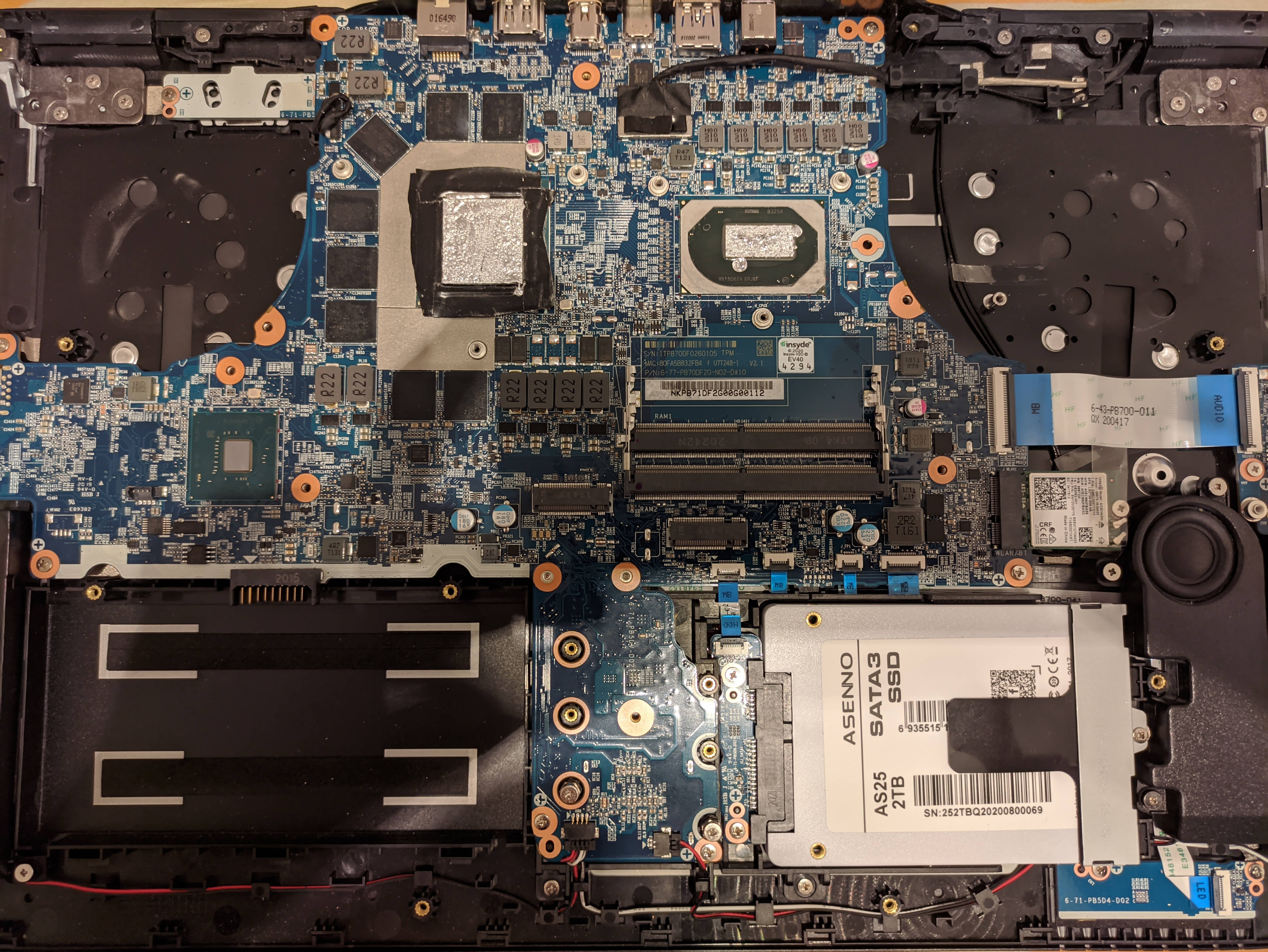
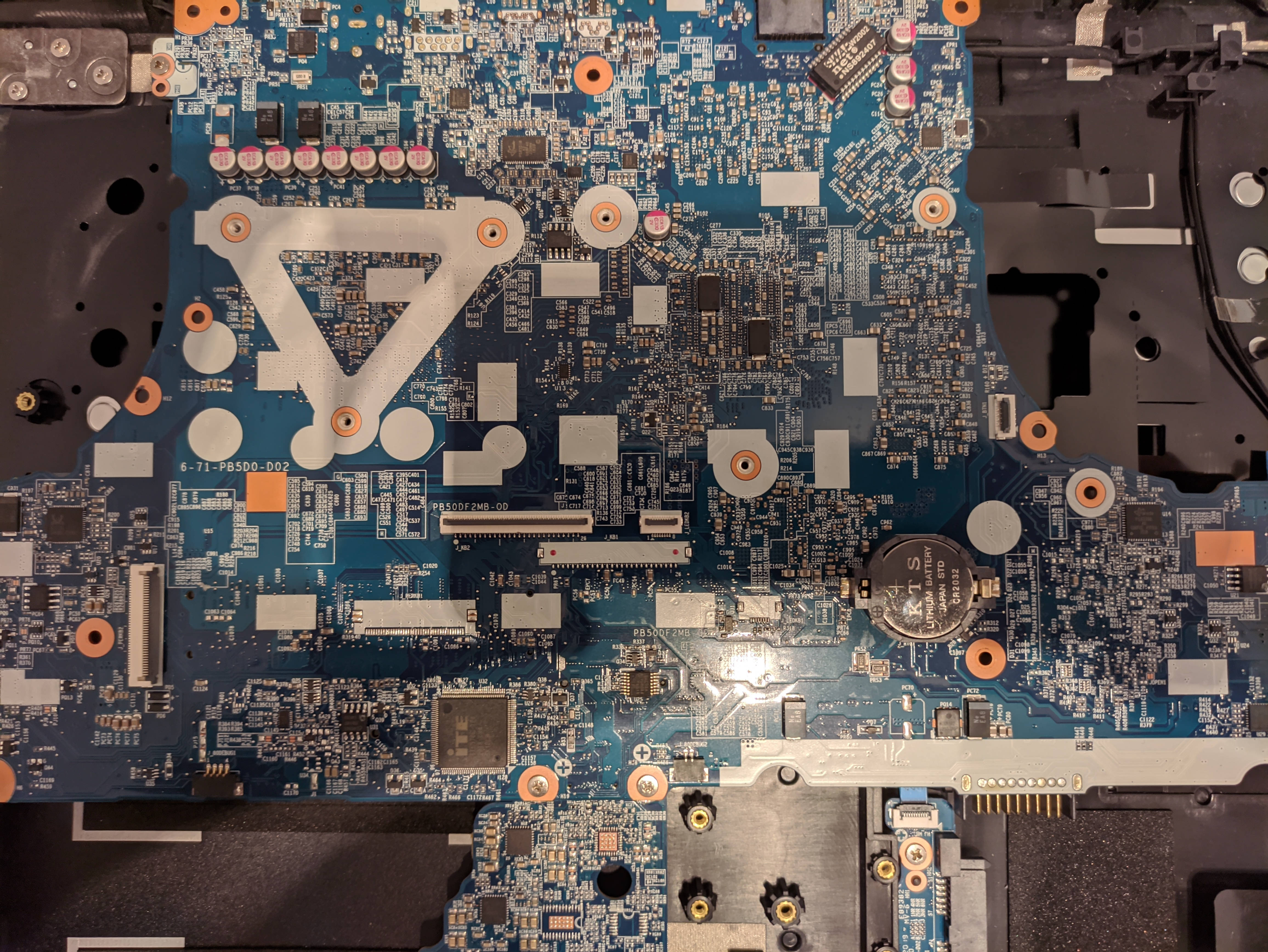
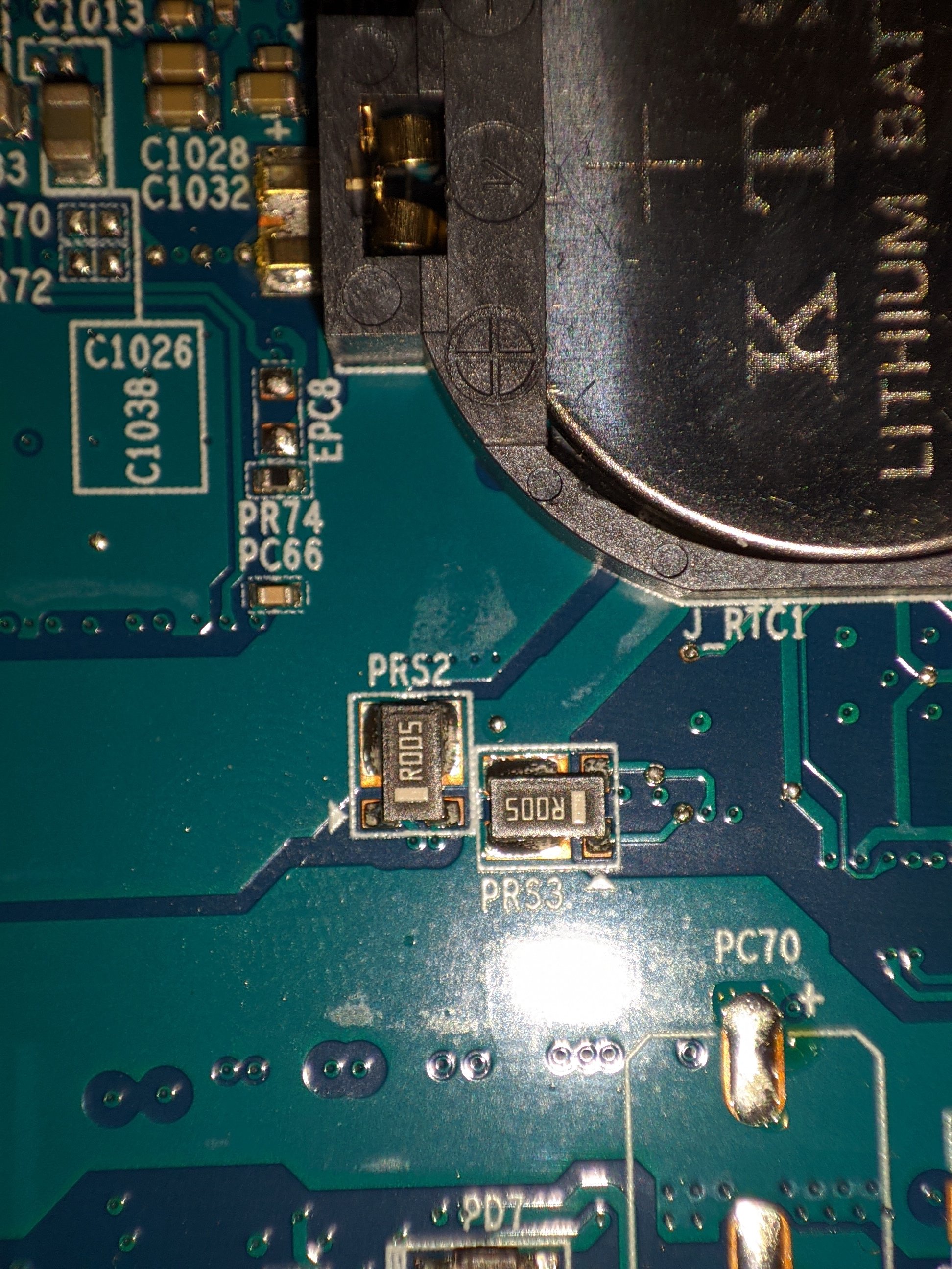
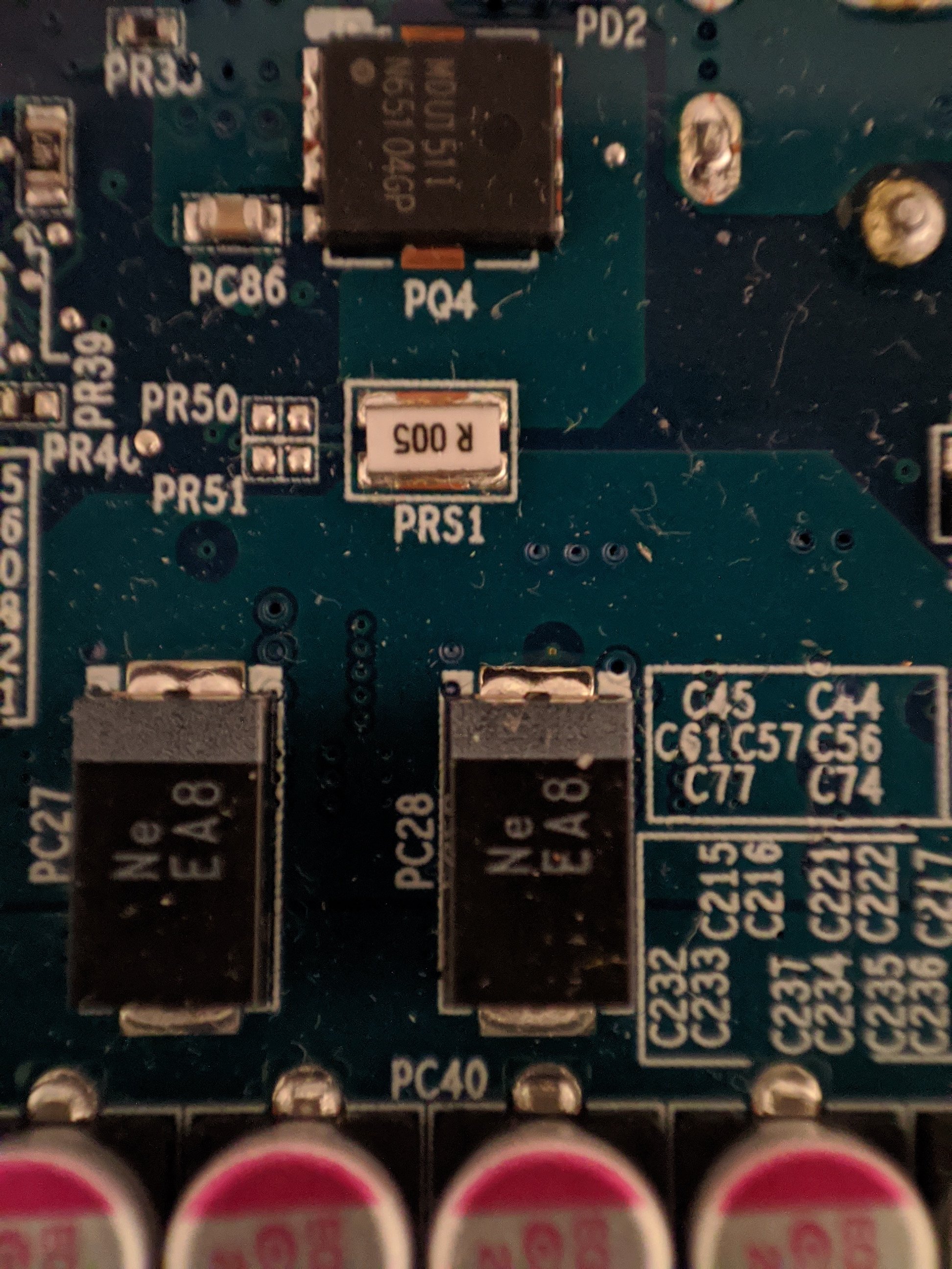
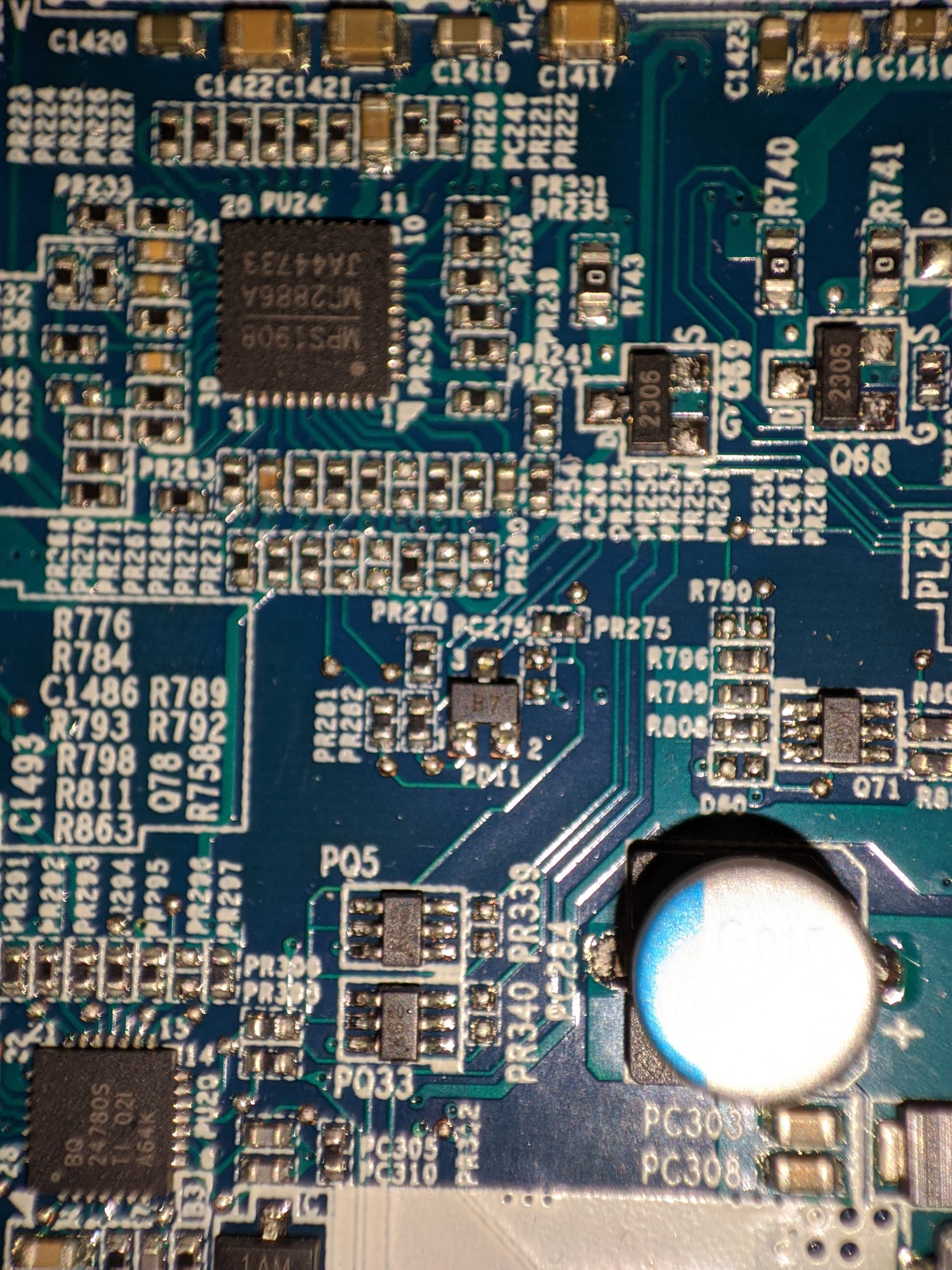
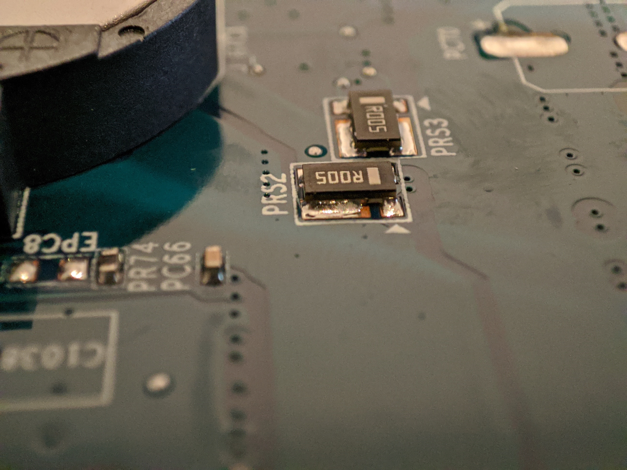
Hello, I'm thinking about doing the shunt mod for my laptop (Clevo PB71DF2-G), and right now I'm trying to locate the shunt resistors. I found some R005 resistors but I'm not sure if they are the ones I'm looking for. I'd be glad if someone can confirm it in the pics. There is 2 resistors near the cmos battery, and 1 at the top left of the board.
Thank you guys.
-
Attached Files:
-
-
Those 2 are likely the correct shunt resistors.
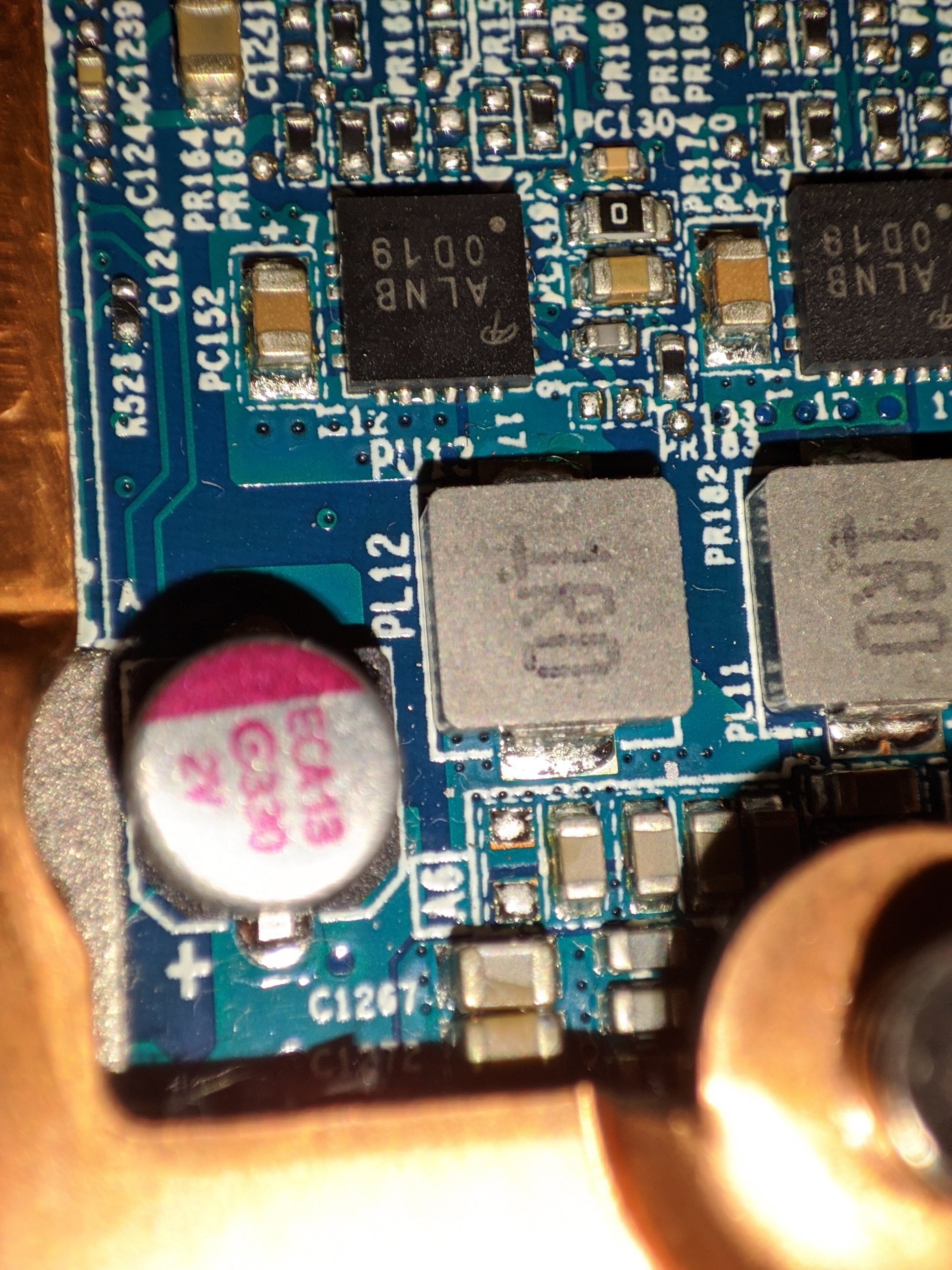
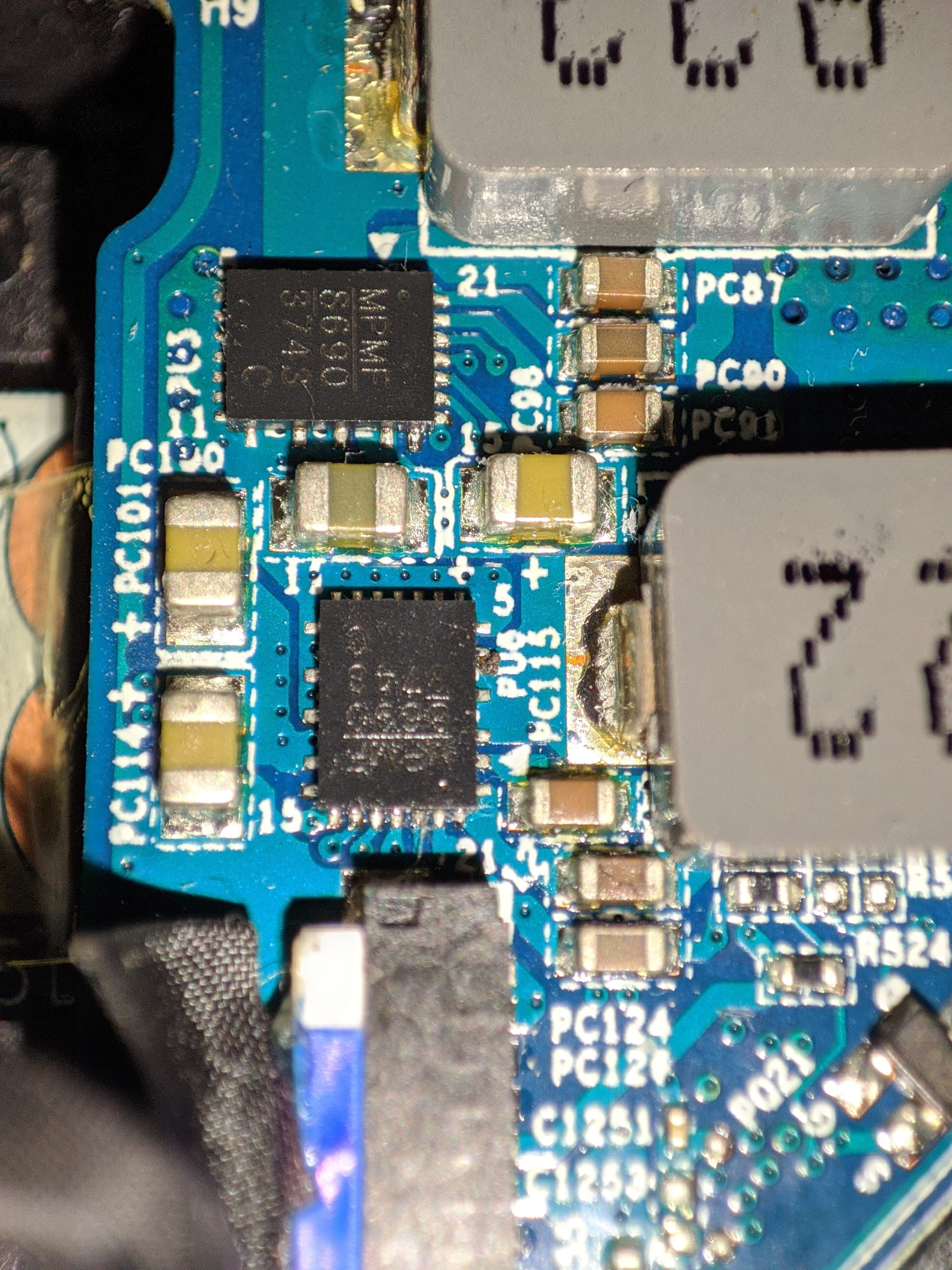
Could you take another picture of the gpu vrms, i need to be able to read the printed text on them. -
Thanks for the confirmation about the shunt resistors. Here is some pics of the vrms.
I already have those resistors : https://www.digikey.com/en/products/detail/te-connectivity-passive-product/RLP73M2BR036JTD/4032597
Do you think they will work ?
Also I'm wondering about the soldering. The only other shunt mod I did was on resistors with contact on both sides. It doesn't seem to be the case for the shunt resistors for this laptop (there is no "metal" parts on sides on top of the resistors). Will it work the same or will I have to do another method ? Sorry if that sounds dumb.
Edit : Currently my GPU (2070 Super) never exceeds 70C, so I think I have some headroom for improvment
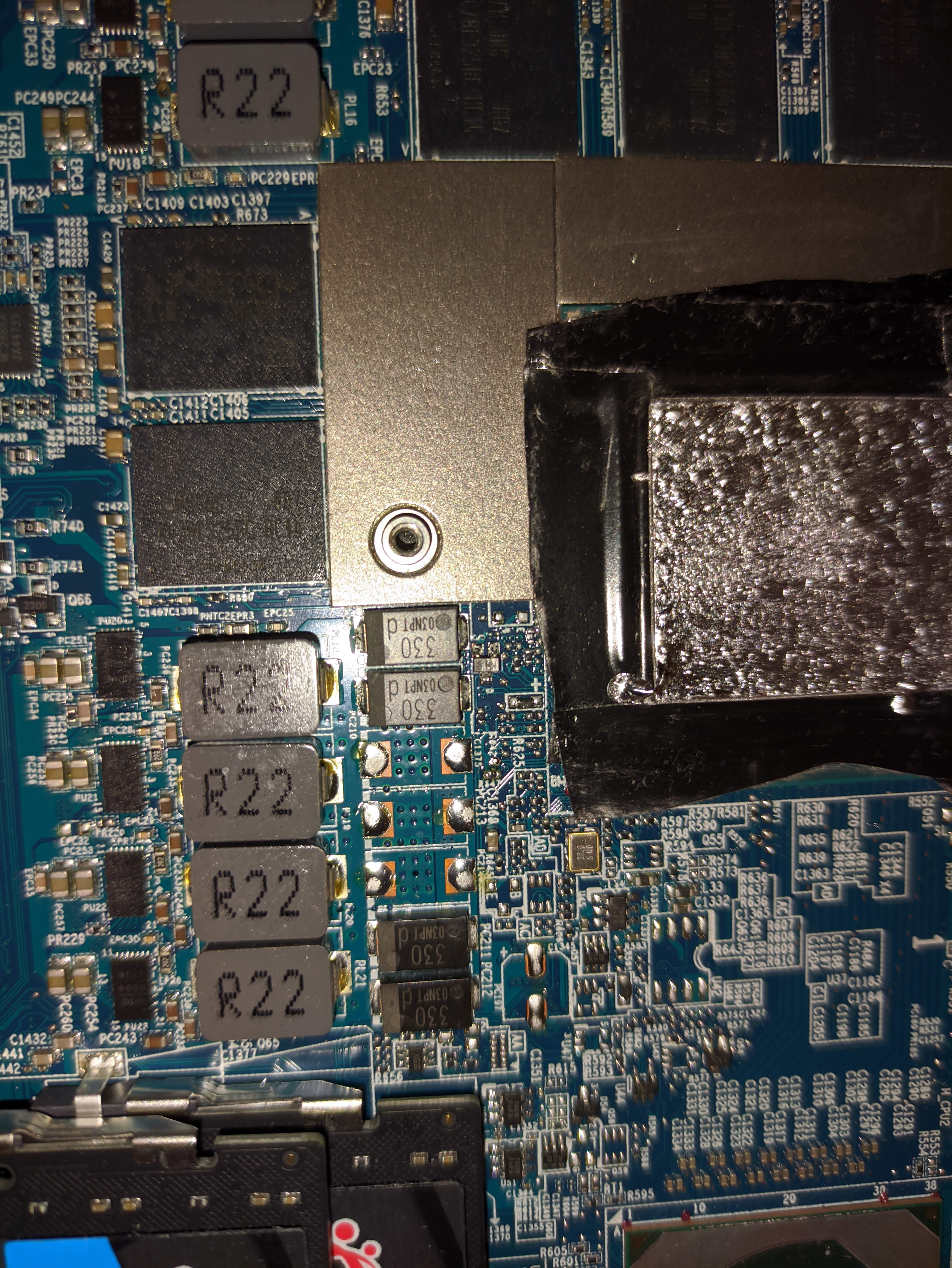
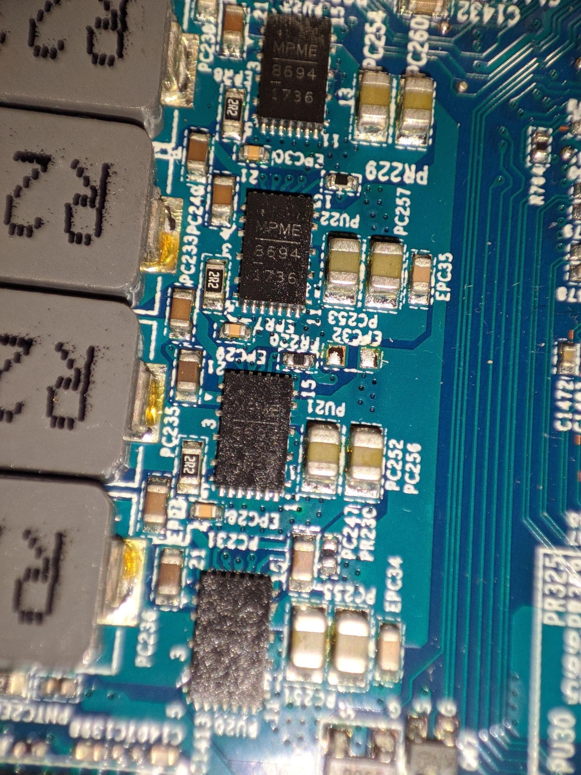
After some research I think I misunderstood what vrms were since all this time. I thought it was vrams. I joined new pictures, I hope it is what you're looking for.Attached Files:
Last edited: Nov 10, 2020seanwee likes this. -
-
Yeah youre good to go. the vrms should be able to handle 150w before needing a heatpipe over them.
Why did you get 36mohm shunts btw? Soldering those in parallel would only bump up the tdp by a measly 15-16w to 130-131wRinkutux likes this. -
Thank you !
I just already had them for another shunt mod I did before, I didn't get them for this laptop in particular. What shunts would you recommend for the best result? Also if I bump the tdp too much, isn't there a limit with turing that prevent the card to use maximum power ? I think I've read that somewhere.
So basically I only have to solder each shunt on top of the R005 ones as usual, right ? I'm just confused about the look of the R005 shunts, where should be the contact points ? I don't know resistors enough to not sound like an idiot. -
Too much would be using R001 resistors or directly shorting the shunts.
I would recommend replacing the stock shunts with R004 shunts outright for a 25% tdp bump. R003 would get you to closer to desktop performance but you'll need to get heatpipes to transfer heat away from the Vrms.
Also you want to solder across the shunt resistors, wide side to wide side.Rinkutux likes this. -
I'm not comfortable enough with this for replacing the stock shunts outright. For the last shunt I did I simply put the 36mohm resistor on top of the R005 one and solder on the sides from the base to the top to make contact. Is this enough ?
Also I'll probably look for 0.02 ohm shunts to use on top of the existing ones. -
Its actually safer and easier to replace the stock ones outright. That way you ensure the stock ones are undamaged from the soldering. It'll look cleaner and have less chances of developing a cold joint.
-
Oh alright I might try it. Do you think I can replace the stock ones with my 0.036 ohm shunts ? If not do you have any link or a reference for the correct resistors to use ? There's so many different properties.
Thank you -
No. That will reduce the tdp.
Also I just calculate the final resistance of the resistors to see how much more power it will allow you to draw.Rinkutux likes this. -
Can I use something like this to replace the stock ones ?
https://www.newark.com/panasonic/erj-m1wsf4m0u/resistance-0-004ohm/dp/27AC4861?st=erjm1wsf4m0u -
Those arent the right size and shape. Look for susumu ones.
-
I see, thanks. What about these : https://eu.mouser.com/ProductDetail/754-KRL3216CR004F-T1
-
I would solder 15 mOhm or 20 mOhm ones on top. Although personally, you're working on a laptop so I would want this to be reversible easily without something going wrong.
You can also alternatively, just use MG Chemicals Silver conductive paint, which works like a ~15 mOhm shunt. You have TWO ways to use the conductive paint: (and use a toothpick with it).
1) to "attach" the new shunt on top of the original (I would use a 15 or 20 mOhm shunt). For this you want as little paint as possible AND ideally, you want the original shunt's edges to be completely flush with the center. This makes stacking work well without soldering. Just apply a VERY small amount of the silver paint to the edges of each shunt, spread it around, then stack the new shunt on top. Then let it dry 15 minutes. Check that it's secured after it dries. If it's secured, follow up with a little liquid electrical tape (easily removeable with alcohol).
2) If the original shunt has 'depressed' edges that are lower than the middle black part, it's best just to paint the entire original shunt, rather than trying to stack, due to the extra gap that would make you use more paint to bridge the gap. In this case, you're best off painting the entire original shunt and bridging the two edges completely, only with paint, and not stacking at all.
Just make sure you 'scrape' the edges of the shunts (the silver part) with a small flat bladed screwdriver first, to remove any conformal coating--you want as little resistance as possible. Then use the paint I listed and a toothpick and make sure the edges of the new shunts contact the edges of the originals.
Some shunts are completely flat. Some have the edges slightly lower than the middle. You may have a slight resistance increase from that (maybe ~10 mOhms) if the original shunts are not fully flat.
This is what I did on my RTX 3090.
https://www.amazon.com/MG-Chemicals-Silver-Print-Conductive/dp/B01MCXW1Y1/
And a toothpick. And some liquid electrical tape if stacking.
Don't listen to the "YOU MUST solder or you are a homeless bum worthless beginner not worthy of overclocking" crowd. This method works fine and has been tested by two people. -
That's very interesting. I'd avoid soldering if I can since my solder skills aren't very on point. Does this method also work with liquid metal ? I have some at home right now. I also have a silver conductive pen, would drawing a stripe between each sides of the shunt work ? Otherwise I'll try to get silver conductive paint.
Few questions :
On the first method, when you say "spread it around", do you mean covering the whole shunt ?
On the second, painting the entire original shunt means painting only the black part ? And then joining each side with paint ?
Also, do you have a link for a good 15 or 20 mOhm shunt that would work ?
Thank you !
Edit : Seems the silver paint you linked is only available in US and won't ship in Eu. Do you have some alternative ? I can't find any sadlyLast edited: Nov 10, 2020 -
First time I've heard of this method, thanks for sharing.
-
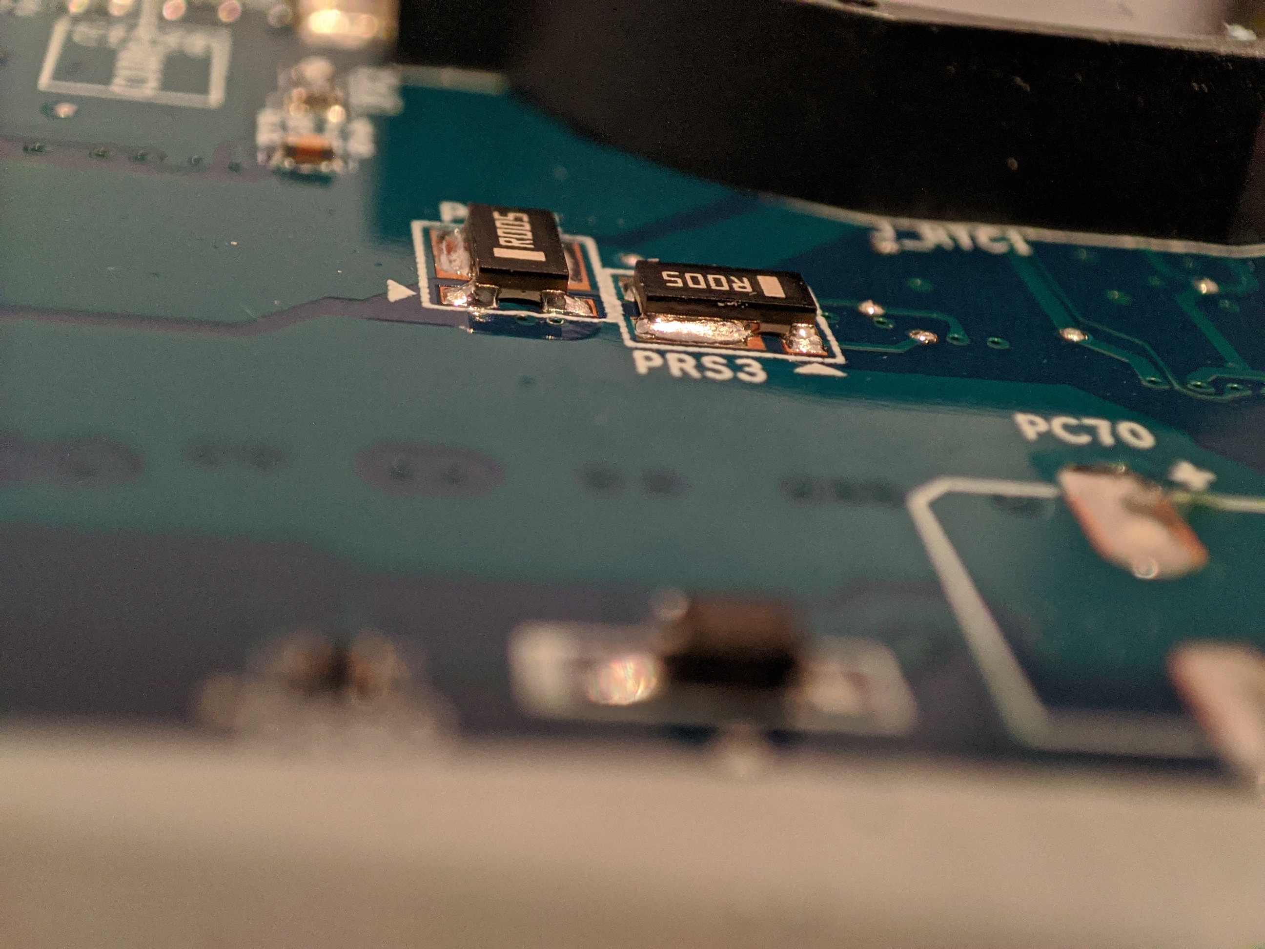
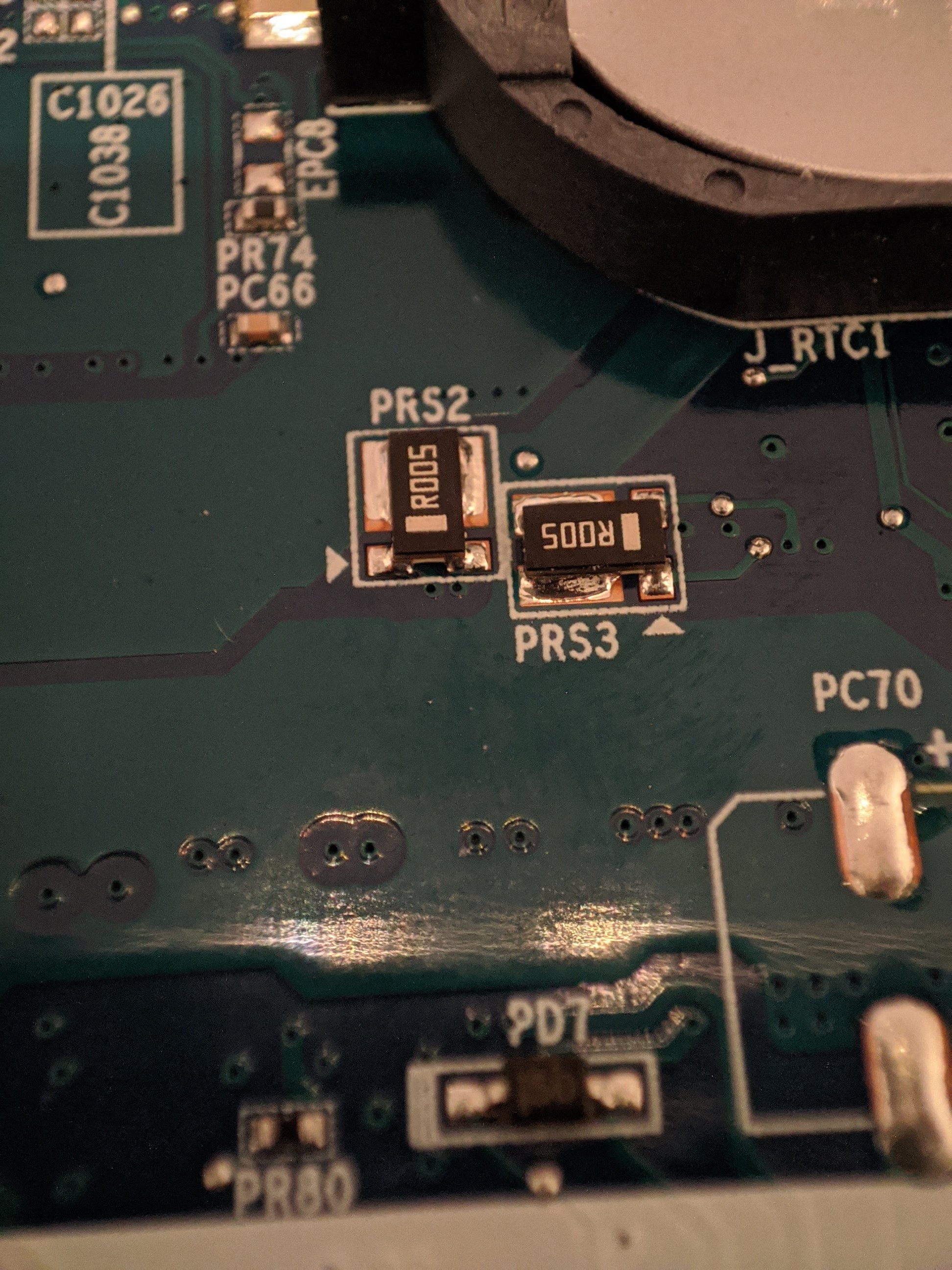
Alright I wanted to look closely to the shunts but in the end it doesn't seem to be "silver" edges for contact. New pics joined. So where are the contacts to solder/paint another shunt on top of them ? Should I solder/paint it from the base ?
Attached Files:
Last edited: Nov 11, 2020 -
-
Liquid metal alloys with the solder and makes it very brittle and soldering anything back again will be a PITA, dont use liquid metal on the shunts unless for a quick bench run...
You need to use some pieces of cooper, or just replace those shunts with new lower value resistors.FrozenLord and Rinkutux like this. -
Okay I'll stay away from liquid metal then, thank you. One more stupid question, is there any difference between those 2 resistors ?
https://www.mouser.fr/ProductDetail...=sGAEpiMZZMvdGkrng054t4qCYjCSzmhRVhT/0a57Su8=
https://www.mouser.fr/ProductDetail...krng054t0c0U24Fa/v2EGrf%2BvT5ErtsEv/VT/BdtA==
The "horizontal" metal lines confuses me for the susumu one. Can I replace my current shunts with any of these ? -
Its a rotated footprint, so only the susumu ones are the correct footprint, the Yageo one is the regular footprint and wont work on your laptop.
-
Alright thanks for the clarification. I never dealt with reversed footprints before, I guess they are not so common. I ordered the r004 susumu ones. I'll probably just replace the stock shunts with them. I'll let you know how it goes. Thank you all !
seanwee likes this. -
Okay so I had hard times trying to desolder the stock shunts, so I just removed the black plastic "hat" and soldered two 0.02 ohm resistors on top of each original shunts. I jumped from ~4700 in Unigine Superposition benchmark to ~5200. It's like a 11% performance bump. Not sure if it's the expected boost but I gladly take it
") Last edited: Nov 21, 2020Falkentyne likes this.
Last edited: Nov 21, 2020Falkentyne likes this. -
How did you remove the black plastic "hat"?
I had no idea that was even removeable! -
I had no idea neither, I just accidentally removed it while trying to slowly pull the shunt, leaving only the metal conductors on the board. So when I saw that I decided to solder the shunts on top on the original ones instead of replacing them.
-
Ok so now I feel like I have some power issue. When my GPU load is at 100% and my CPU around ~50% in game, the laptop starts to throttle for 2-3 seconds. I assume it's my 230W PSU not being able to provide enough power. What do you think guys ? I tried to look for 330W PSU but I can't find any compatible with my laptop model. I'm on a Clevo PB71DF2-G and I can only find 330W PSU with 4 pins power connector or Alienware ones that don't use the same connector than mine. I can't find any adapter neither. Is there a solution for that ?
-
Hey there. I have an MSI GS65 8RF with a 1070 max q that has an 80w TDP. I was able to successfully cross flash a 90w 1070 mobile vbios via nvflash but unfortunately the hdmi and dp didn't work afterwards. That's why I would like to try and do the TDP mod either through the programmer or through a shunt mod. If you don't mind, I would just like to ask as to how much additional TDP do you think can the VRMs safely handle? And as for the shunts, I've tried looking for an R005 resistor on my board but so far the only one I could find is underneath the board near the battery connector. On the flipside of the board, I see two resistors which are not labelled but are near the INA3221 near the cmos battery, could they be the shunt resistors? I've attached some pictures for your reference. Thank you.
n.b.
I've already done some improvements on the laptop's thermals:
- repasted the CPU and GPU with LM
- replaced the pads with Gelid Extreme and some K5 PRO
- vacuum coolers on the GPU and CPU exhaust vents
I am also planning to put an additional heatpipe from the VRM section to the GPU fans.
![[IMG]](images/storyImages/IA1FPqs.jpg)
![[IMG]](images/storyImages/q15M2P9.jpg)
![[IMG]](images/storyImages/MfyNt0w.jpg)
![[IMG]](images/storyImages/oTSws8a.jpg)
-
That looks to be a doubled three phase configuration. Should be able to handle some shunt modding. You can get R004 resistors to replace the unlabelled resistors to raise the power limit to 100w.
-
Understood. Thanks, appreciate it.
-
Probably i should ask after all..
Did anyone mess with Clevo MXM RTX cards, most specifically a RTX 2070? Any success, any advises? -
so only way to bybass this is to shunt? (ge75 2060)
and is there any vbioses for gl702(1070 115w) or i can use the tdp tweaker? (also got same error nothing changed, invalid firmware -
I still can't find a proper way to get a psu capable of delivering more than 230w (the laptop power throttle since the shunt mod during gaming sessions). I found some 330w but the connectors are either 4pins Clevo or 7.4*5.0mm Dell ones. I need a 5.5*2.5mm adapter but the only thing I found is this : http://www.bixnet.com/cntx75.html but it's stated that it won't deliver more than 120w using this adapter. Does someone faced this problem before ? I need some help to get through this.
-
I'm using one myself. Get adapters that are a solid jack, not ones with cables.
What laptop are you using btw? Although I'm using a dell 330w brick I can't go above 230w total laptop power draw still because Msi limits the power draw to 230w in the EC regardless of what power brick you use. -
I'm using the Clevo PB71DF2-G. I'll try to get a jack adapter. With the shunt mod my GPU is at ~140w and my CPU is around 60-70w during games if I don't limit it. And when I play games that are GPU and CPU intensive, the CPU just throttles down to ~10w for like 5 seconds so the GPU isn't capable of running well with a 10w CPU. The throttle doesn't happen when I limit my CPU to 40w, but I'd like to avoid doing that since I have a powerful CPU.
I have no idea if Clevo systems have a power draw limits in the EC. I hope not. -
Alright I finally got a 330w PSU but it's just barely better than my 230w. I can get a few more mhz on the GPU before the throttle happens again. Probably limited to 240w or something in the EC. Is there anyway to remove that limit ?
-
Man I wish I could get mine to raise the TDP like the 2019 Omen 17t could. I tried NV Flash with the custom vbios from the thread in the HP section but it doesn't change anything. The TDP still maxes at 150w with small jumps to 160w or so.
-
A routine check
Did someone find a way to uplift the Clevo RTX2070 powerlimit yet? -
Shunt mod is still the only way for anything RTX20xx.
-
Without Prema bios max power draw is limited by EC at least with some Clevo models if not all. There have been threads about this in the past.
-
Hi All!
I would like to upgrade to 2080RTX in my Clevo 870DM3. It has vapor chamber so cooling cannot be an issue to shunt mod tha card. Could you help where I can order them? I would need 4 resistors I guess and which ones could be proper? R003 or R004? I have a good engineer friend, he can replace them with professional machines easily. Thanks for your help in advance! -
Eurocom sells them on ebay for an arm and a leg.
Falkentyne likes this. -
Hello there, I'm new to this forum and I was looking for this thread since days. It's really cool stuff, indeed!
I'm having a couple of questions before buying a decent ch341programmer. Maybe everything is written in the thread, but it's really huge and I haven't looked everywhere (even if I used the search button, of course).
1) I'm on a MSI GT73VR 6RE (i7 6820HK / GTX 1070) and so I have a 230W power supply. Is it possible to flash the vBIOS featuring the 150W power limit or is my power supply too weak? I noticed the CPU can use about 70W on turbo (4GHz on all cores).
2) if it would be possible, how much performances will increase (more or less, of course). Will I be able to gain 10%? Consider on full load my gpu doesn't go over 68° on 1743 MHz
3) talking about power supply, I saw someone uses a 330W with the GTX 1070 but still throttles over 230W power consumption. Is it because laptops featuring 1070 assumes to use a 230W PS?
Thanks to everyone who will answer -
Yes you can flash it to 150W. Don't go above 150W. Also you need to use RW Everything after a power off, to change EC register location "E3" to 11 (default value is 10 for 6820HK /skylake GT73VR And 90 for GT73VR Kaby Lake systems, so 7820HK users would want 91 here, although "11" still works on a 7820HK), which is for the GTX 1080 (330W) power allowance. This will stop excessive battery drain from pulling close to 230W. If you don't do this, you will lose like 10% battery every 20 minutes or so if you're pulling about 180W or higher.
(the 230W PSU can handle about 245W before it shuts off)Vistar Shook and Surax like this. -
Fine, that's perfect. I have my programmer on his way, it should be delivered today. One more question: my GT73VR is from 2016 and featured a faulty 1070. I sent it to msi about a couple of times and they said they replaced it, but I don't know if that's true, because they returned me with the 3A vbios. I didn't bother too much and I said within me "oh well, it works, doesn't matter if they didn't replace", but now that I'm going to do this vbios flash, I don't know if this can give problems. Is there any way to check if I still have a faulty one? Should I wait until Monday and contact msi to ask informations giving the gpu SN?
-
now you have 115w long usage - 70C or similar
no need 150w ,.,.,.91C is max for long usage or lower"
here exist 125w vbios + working cert "nvflash"
for 150w need good PADS // Thermal paste // EC mod
115w or 125w - ideal 0.893mV - 1850-1900mhz lock"+200 core OC ,.,.vram no need -low TDP"
i think ,..,no need more
,.,notebook performance is ideal HALF/SYNC -60FPS lock
or some games /// G-sync 75-120 FPSSurax likes this. -
I don't know, I tried 3D Mark stress test and it seems the gpu doesn't want to hit 115W at all, just keeps around 100/105W. For pads, I have brand new Gelid Extreme (or Ultimate, can't remember the name) ones and Thermal Grizzly Cryonaut as thermal paste.
Talking about voltage, it seems the gpu can hold 1.063V with no problem at all, so the gpu seems a working one. Any idea on why my gpu doesn't asks for 115W in 3d mark? -
full stress
MSI KOMBUSTOR -3d render "ms01" 4x tesselation + full screen "low usage + full vcore" // 32x tessellation "under power limit"
second VRAM 6500MB GL test "under power limit usage"
30min -check results ?? dont brick machine
85C max !! or stop test
115w - real 0.750V or lower in full load ,,gaming -0.893V MAX "small power limit"
no need 1V up for LOW usage
or any game 120FPS - more hours gaming
WAR-Z is ideal for burn test
Last edited: May 15, 2021Surax likes this. -
Perfect, thank you, I will try later
-
ideal is OSD in game + voltage // power limit
i have same card on LM - 84C is no problem for 125w long usage !!! -
I haven't found lots of parameters you gave, so I thought it was a CLI command, but combustor started just normally, so I'm just using it through the GUI. It is using all 115W, keeping voltage under 0.9V, don't know why. Temps are under 60° with turbo boost on. I'm going to keep it up for a half hour
-
TDP -115w is low / more usage - lower voltage
but best is OSD or HWINFO
60C ?? it's very good results
edit.. .,,example from my GT75 + 125w load
VRAM test
extreme load / slow fan curve for full stress + cpu stress
View attachment 189336
edit ,,gaming stress
MSI_01 stress - GPU / full screen
+ cpu burner "4 cores only" 50./. usage "most games"
game stress ,.,.or stability verify "x8 cores"
// additional is VRAM test
select GL6500MB --full vram + CPU
heavy game
fan setup ? headphones + cooler booster
or target is max 3000rpm before startup helicopter
20-20-30-50-60-100 is my GPU curve "fan setup"
3000RPM gaming /lower idle ,.,.max rpm under 90C
example
Last edited: May 15, 2021
Mobile Pascal TDP Tweaker Update and Feedback Thread
Discussion in 'Gaming (Software and Graphics Cards)' started by Coolane, Jun 20, 2017.