I don't understand any of the stuff Next3R is telling you.
8A vbios limits the card to 0.875v max.
3A is full voltage. If you pulled 1.062v and it didn't crash, your card is fixed.
Just flash 150W and remember to set TDP to adjustable in the editor. Don't forget to press the "preset" button for the "advanced" power limits once, as that is required!. Just go back to the basic power limits after and you can set it to 115W base, 150W max.(This was simpler in the older 1.1.3 version). If you forget to press "preset", this will not make the mod work reliably. (if you did this right, the "advanced" power limit settings will show 19200, 242000 and 137600.
If you later get a 330W Delta PSU (recommended), then you can set the range to 150W default, 230W maximum (as always you will need to run RW Everything, go to the EC RAM page, and change register "E3" from 10 to 11 on every boot. It's possible to make a batch file to do this by a simple mouse click.
Mine looks like this.
@echo off
cd\
cd /d C:\Program Files\RW-Everything
Start /b rwe.exe /Command="WEC 0xE3 0x91"
timeout /t 2
taskkill /f /im rwe.exe
For your Skylake you need to change 0x91 to 0x11
-
-
Thank you Falkentyne, youe explanations are always really good LoL
Now, I'm stressing a bit the hardware, as is, then I'll flash the modded bios (maybe after working) and try the EC editor. Is it worth to spend 55€ to get a genuine 330W delta PS? I'm planning to build a PC in later 2022, it's just to know how many performance I'll gain from a PS upgrade. And using the modded bios, will I need to edit the voltage curve the get more stability? -
for gpu is best any long gaming ,.,temperatures is raised slowly + need cpu stress
HWINFO in background
https://www.hwinfo.com/
SENSOR
and any games on 120FPS use this gpu fully
or simulate similar usage in MSI KOMBUSTOR
determine need or not need 150w
125W is possitible -normal flash NVFLASH ,,.no need EC mod
tested
good luckSurax likes this. -
I think I'll manually flash the 150, using the needed power everytime. I'm stressing gpu using kombustor and temps raised to 68° NO COOLER BOOST, just auto fans
-
In this current GPU market where a RTX 3090 is $3,000, a RTX 3080 is $2,000, $55 is a complete bargain.
230W through a GTX 1070 is about 15% overall higher FPS than 115W. Considering the current market, I don't think you should complain about the price.
(And yes, the MXM slot CAN handle 230W directly through the slot. Just remember to buy some Arctic 6 w/mk OR Gelid Extreme 12 w/mk (1mm thick) thermal pads and re-pad the GPU VRAM and VRM's).
No you don't need to touch the curve. I can run +145 / +500 on my card without a problem. -
I have a brand new thermal grizzly kryonaut as thermal paste and 0.5mm gelid ultimate pads (should be 12.5 w/mK). Do you think I should be able to use them by putting two one on the other?
-
0.5mm is too thin.
You want 1 mm. And do not stack pads. Stacking pads should only be done in emergencies (example if you needed 2.5mm and it doesn't exist and you tried 2mm + 0.5mm). But in that case you can use Gelid Extreme (NOT Ultimates) and use 3.0mm version which will compress down to 2.5mm because they are soft enough (This is just an example!). -
OK fine, then I'll order on Amazon 1.0mm pads. I think I will mod the vbios to be able to reach 230W, keeping it to max 150, so when I'll buy the new 330W PS I'll be able to use the board without keeping it out another time. Is it possible or there is too much gap between 150 and 230W?
-
Ok in this case, set the TDP limit to adjustable, default value=150000 (150W), max value=230000 (230W).
Don't forget to press the "preset" button at the bottom and then check the Extreme Power Limit, for the 3 values I mentioned in the above post.
Do NOT change these values manually (except to the values I listed) and make sure default and max are the same value.
These values are still documented, and similar values existed in the Maxwell Bios Editor. The only thing that was known was that these were "PCIE Power rails" of some kind, but its unknown exactly what values were what. I DO know that the very first value, if it's not changed from 16200, will cause premature power throttling. The second value, I'm not sure. However in a much older version of the Pascal Editor, I believe this value was left at default (which I believe is 181000), and I noticed power throttling at 150W, in PUBG randomly, even though I had the slider set to 200W.
When I manually set it to the GTX 1080 (mobile) default limit (242000), all the power throttling stopped.
The third value's default limit for 1070 is 76700 and preset sets this to 137600
From what I've seen on the Ampere video cards (Ampere Bios Editor), there are multiple power rails, including 8 pin power (not the same as TDP, but is the maximum a single 8 pin can draw, but it seems this limit can be exceeded), memory power, SRC power (SRC seems to be power plane input source, which limits what an 8 pin power rail can draw total), and GPU Chip Power.
I'm taking a wild guess that the first value is God Knows What, the second is "SRC" and the third is God knows what.
When I looked in HWinfo (latest version), it looks like on the MXM 1070, that GPU Board Power is equal to SRC + 3W, and the PCIE 3.3v reading is 3W
The first extreme power limit "may" affect something on Battery Power as well, but Coolane said in a much older post, that if this limit isn't changed from 16200, the board can't exceed 115W. But HWinfo64 doesn't show any input power that low at all. So well I don't know?
One of my chinese friends (a chinese student who was studying in UK) used the 1080 Ti "advanced limits" on his GTX 1080 MXM card and it burned out the VRM's. He got the VRM's replaced but there was damage to the mainboard also and the card wouldn't work in it, only the Intel GPU worked.Surax likes this. -
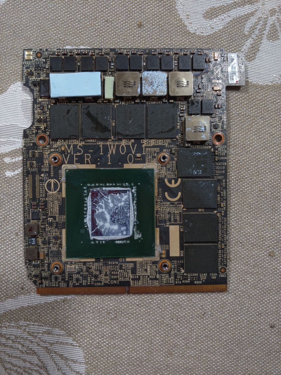
I've just taken out my gpu and... ver 1.0? WTF? Shouldn't be 1.2? And don't know why, every single letter on the pcb is brownish, like if it's a really old card... Mhhhh.... I don't know if msi really changed it when I rma-ed my laptop
EDIT:
I've just finished to repaste and repad my 1070 and works like a charm on 150W. It seems I have not to change the EC parameter to match the 1080 eveverytime I reboot, just did one time and worked after a reboot.Attached Files:
Last edited: May 19, 2021 -
-
This is what the graphic cards that were repaired using the "oven baking method" look like.
-
Yeah, it seems, but I don't think in msi do this kind of things lol
-
Hi. I have notebook hp pavilion 16-a0021ur. I want to expand the thermal package. Up to 80w. Can I flash vBIOS from similar mobile graphics chips? For example, 10DE-1F11 or 10DE-1F15.
I have tried modifying my vbios with "Mobile Pascal TDP Tweaker 1.21", but I cannot pass verification in nvflash. My dump is correct and successfully flashed through nvflash. I understand that the modified vBIOS can only be flashed through the programmer. -
Yeah, you understood well: only signed vBIOS can flashed through nvflash, it's an nvidia protection system. If you have a dump of the original and the hardware programmer, you can try to flash the modded one and see if it works. If it doesn't, then just reflash the original one. I'm just supposing, maybe you should wait for someone with more experience to reply
-
10DE-1F11 or 10DE-1F15
same card model only TDP different ??? oem vbios + cert
nvflash -6 new.rom
or what have message in NVFLASH ?
cert 2 error -- programmer
ID or subsystem is possitible overwrite in nvflash
edit,,subsystem is OK change ,,ID is RISK !
edit,. max q ,,,i not recommended tuning ! -
gpu-z ,.,.,.send screen here ,,.what have MAX q rtx 2060?
10DE 1F12 ???
/////
10DE 1F12 - one is 75w
or 65w lock variant
10DE 1F11 - around 90w "different card"
10DE-1F15 --some is 100w
but all is different HW !
fast check available vbios on techpowerup
edit,.,translation repair -
Yes. 10DE-1F12.
![[IMG]](images/storyImages/image.png)
-
75w max is OEM .,,.on vbios on techpowerup --possitible flash in NVFLASH
max q "**** hw" locked ,,.,.any TDP raise --possitible HW defect !
oem vbios name or TDP now ?? 65W lock or this 75W vbios ?? -
73w.
-
its OK ??? maximum from all available vbios on web
more is RISK for your HW "10DE-1F12"
the others are different cards "more resistors" ,.,.not only TDP
and CUSTOM TDP mod ?? still MAX -q -- possitible BRICK
,.,.try only AFTERBURNER "custom curve + max OC for CORE"
this is all // safe option
some RTX is max 87C or lower
good luck -
My RTX max 70C.
-
sometimes try combined stress
GPU full load + CPU --for gaming notebook
.,similar like long gaming -- 1h or more
and still have MAX-Q HW - here is minimal space for MOD
most time is this HW of lower quality ,,less parts --lower TDP LOCK
edit ,,,.real temperatures points
GPU-z - advanced info
or NVSMI -from drivers "CMD" -
It is very sad. But thanks for the tip. My inner accelerator is crying.
-
-
still you have good gpu RTX2060 ,.,,is OK .D
voltage limit + max OC when need -- more core clock "no power limit"
max-q 2060 review
https://www.notebookcheck.net/NVIDIA-GeForce-RTX-2060-Max-Q-Graphics-Card.386286.0.html -
Does anyone succeeded with OC MXM Pascal Quadro cards ?
-
it's a dead end
-
Hello I made a shunt mod on my clevo n950tc replacing 2 smd components 0.005 with 0.004. The frequencies of the gpu 1660ti have increased slightly (almost 2000mhz at a minimum voltage of 0.975 mv) and now in the Time spy test I am gaining 6100 points instead of 5600. The gpu power circuit consists of 4 phases in the core (4 mpkh8694 1909 together with 4 LR22) and 2 in memory (2 mpkh8694 1909 together with 2 LR22). My question is, can I move the tdp bar higher by replacing smd with 0.003, without harming my vrm's. And how can I check the power output of my gpu 1660 ti now? As I understand it, after the shunt mod, it has now become impossible programmatically. Hvinfo also shows tdp gpu no more than 80 watts. I solve the problem with the gpu temperature by buying a new version of the cooler with 3 copper pipes for the gpu rtx 20 versions ... Will my vrm's handle more power?
Last edited: May 31, 2021 -
I am interested in shunt modding the 1660 Ti (80w limit) in my Clevo PB50RC.
I've been reading posts by @seanwee and wonder if he'd be interested in offering some help to both of us. I would be very grateful for any help. I'm not sure if this is the right thread since it's not Pascal.
My PB50RC has an i7 9750h, no thermal throttling thanks to LM, no power throttling thanks to ThrottleStop. It runs a bit hot under full load (80-85 with 4GHz turbo/all cores), which I hope to reduce by replacing my heatsink array just like @Romkarommdg -- here's a picture of what I'm getting, going from version A to B (not from this reseller but the picture is good): https://www.aliexpress.com/item/4001296577414.html
I didn't replace the stock thermal pads when I first applied LM, so now I'm looking at Gelid or Fujipoly pads when I replace the heatsink.
The 1660 Ti runs relatively cool, 65c under load with a 210+MHz core and 870+MHz memory overclock. There already seems to be sufficient thermal headroom for the shunt mod, and consider also the incoming heatsink upgrade + high quality pads.
On top of this I'm also replacing my stock 180w PSU with a 230w brick, which I think is the highest I can go due to firmware limitations. From the wall, the system currently draws between 185-205 from the wall under heavy loads (watt meter).
I'm happy to give more details/information/pictures! -
Depends on the vrm cooling. Does it only have a simple large coldplate over it or is it connected to a heatpipe?
If its the latter, it could be possible but a R003 shunt will effectively allow a power draw higher than the 1660ti chip uses. If its the former, you'll need to have some heatpipes facilitating heat transfer away from the vrms to either the cpu or gpu heatsink.
See above. I recommend gelid GP Extreme. They conform better than fujipoly pads which are hard, fragile and expensive and may cause heatsink pressure issues due to their incompressibility.Falkentyne and Papusan like this. -
Thanks, I will go for the GP Extreme. I'll come back with pictures of the VRMs + cooling details and pictures of the shunts.
I think my shunts are identical to the ones shown in this post from last year: http://forum.notebookreview.com/posts/11057920/
The picture of the back of the motherboard in my service manual shows the same two shunts in the same location, but the manual picture is too low-res to be reliable (can't read the text on the board).Spartan@HIDevolution and Falkentyne like this. -
Guys I'm back here to ask some infos. I modded and flashed the bios with the values gave from falkentyne. Everything seems worked but I was busy and forgot about it. Today I decided to benchmark the board (an msi 1070) using 3DMark FireStrike.... Power consumption seems a bit disappointing.. 99/100% gpu usage and it don't even reach 130W (I rweverything - ed the value in 0xE3 offset from 0x10 to 0x11). Is it supposed to be normal? Should I simple buy the bigger power supply? From the wall, seems to dry just about 200W.
Last edited: Jun 18, 2021Spartan@HIDevolution likes this. -
You need to use MSI Afterburner to increase the power limit.
-
I have default power limit set to 150W and i can reach 230W. Sure I need to modify it within afterburner? Opening it, I see it is set to +100 and it can reach +153.
-
@seanwee I've located the shunts and have some pictures of my VRMs and cooling.
I wanted to take a single high-res shot that covered the whole board, but that wasn't possible. I hope the pictures below are sufficient.
https://ibb.co/ncCrY3r (GPU area #1)
https://ibb.co/StJcw9j (GPU area #2)
https://ibb.co/JnXC5rK (GPU area #3)
New heatsink installed: https://ibb.co/D8Kyqc2
I also re-applied Conductonaut and replaced factory pads with Gelid Ultimate. Based on my understanding of what VRMs/SMDs require improved cooling, all the important ones are now covered (the old heatsink covered almost no SMDs except for the VRAM modules).
The shunts are identical to the ones shown by @Rinkutux here and since his pictures are much better than mine, I'll just link to his post: http://forum.notebookreview.com/posts/11057920/
I didn't know that the shunts were so tiny until I saw them in person. I now have some doubts about moving ahead. The dimensions of the shunt are the same as these Susumu ones: https://www.mouser.com/ProductDetai...=sGAEpiMZZMvdGkrng054t4qCYjCSzmhRuqROSoEQnSQ=
Rinkutux said that he managed to remove the black plastic 'hats' or covers from his shunt to expose connecting surfaces, which would allow me to piggyback resistors on top of the board ones, but it's not obvious to me how you would do that. If I can't remove the covers, I'll have to remove the two resistors completely and solder on two new ones. -
If you want to operate with a safety margin on the gpu power delivery, replace the shunts with R004 shunts, that will give you 100w.
I'm less inclined to recommend using a R003 shunt as that will remove the power limit and from what I've seen from the power draw of shunt modded 1660tis it pulls about 120w which is right up against the limit of these vrms. -
Thank you for your help!
I have some practical questions. When I attach the new shunts, is it OK if solder ends up connecting the two pads on either end of the resistor, or do they absolutely need to be kept separate? Here's what I mean: https://ibb.co/zNJzM7r
In some pictures I've seen, solder seems to bridge these pads without issue.
The shunts are very close to each other. Do I need to make sure that solder does not connect the pads of both resistors? For example, if solder on pad 2 (picture) connected with a pad from the resistor next to it.
Might be very basic questions here, sorry. I appreciate your time! -
He was talking about replacing the shunts, which requires desoldering the old ones. This can be extremely difficult for novices, because the PCB ends up absorbing most of the heat from the iron. To easily desolder a shunt, preheating the board is basically a must, and that requires a hot air station to preheat the board, then you can more easily desolder the shunts to replace them with 4 mOhm or 3 mOhm shunts.
I'm not sure how you would stack shunts on those strange shunts like that.
If you can see the pads that the shunts sit on, then what you can do is, apply flux on top of the original shunt, then apply a small solder drop to the top of the shunt, right where the metal part(s) of the new shunt is, then put the new shunt on, melt the solder from the side, and then build a solder 'bridge' going from the new shunt down to the solder pad on the board. Obviously that will take some doing, and you may need some (inexpensive) desoldering wick to clean up some.
Of course one thing that is essential is buying some high temp polyimide 3M tape (Kapton tape) and taping around the area you are working on, to help stop solder from getting somewhere you don't want it to be, from an accident.
Or you can just use a hot air station and heat the board and desolder the originals...seanwee likes this. -
Not necessarily. I have a 2 power soldering iron 20w/200w which can quickly melt solder locally without heating up the rest of the board. The shunts just pop right off.
And yes, I was talking about shunt replacement, not stacking @murby -
Can you link me to that iron?
-
Its this one. https://www.amazon.com/Soldering-El...QQQWSKDK5AV&psc=1&refRID=W3034J7Z2QQQWSKDK5AV
But i got it for $25 shipped
Edit:
found a cheaper seller
https://www.aliexpress.com/item/32641352437.html
The only $20-25 dollar sellers are on shopee which im not sure ships to your countryLast edited: Jun 29, 2021Spartan@HIDevolution, JRE84 and Falkentyne like this. -
LOL, just get a KSGER T12 or a similar station, T12 tips are the most advanced tips yet, the heating element is directly the tip which make it a lot more efficient for large power/copper plane.
The SH72 can be an alternative but you would need to provide your own PSU and it's only an analog control with no lcd showing you the temp.Spartan@HIDevolution likes this. -
Hi! I successfully flashed the bricked bios of my laptop (gigabyte g5 kc) with a ch341a spi programmer. Talking about the gpu mine is a 3060 90-105w, with flashed a tongfang 80-130w bios.
There are routes to enlarge in this direction through the spi programmer and the tool?Spartan@HIDevolution likes this. -
Also if can help: have a same voltage overpowered 230w psu, coming from previous laptop (the actual is only 180w).
Regular bios is modded ..
No one? -
Bro, is it possible to have a copy of the vbios of your Quadro P3200 ? Actually, I'm stuck with an HP model which lacks Bios chip onboard. I ordered a bios chip but I need a valid (a modded or an original) vBios for Quadro P3200 to program it before soldering.
PS: If anyone can provide me a valid vbios for a Quadro P3200 MXM, I will take it. ThanksSpartan@HIDevolution likes this. -
Do you still have your Quadro P3200 on the 17 G5 (I use a 14 G4)? If so can you extract and share the original vbios?
-
You have a couple bios for the P3200 on techpowerupSpartan@HIDevolution and Christian Olivier Andogui like this.
-
Hello guys,
i would also like to mod my 1060m cart too, the power limit is very low even when i downclocked her she trottles permanent. I have a MSI GE62VR (MS-16JB) Notebook and i can read and write the original bios. But when i mod the bios with the "Mobile Pascal TDP Tweaker" and write it i got the Error:
BCRT Error: Certificate 2.0 verification failed
BIOS Cert 2.0 Verification Error, Update aborted
The EEPROM is a WBond W25Q80EW, so what should i do, i dont want to brick the bios, can anyone help me there?Last edited: Aug 3, 2021 -
and did you read the first page at all?
,..custom vbios --- HWprogrammer ONLY
stock is around MAX 90w GTX1060 .,if you find compatible vbios from another model - possitible use NVFLASH -
Now i bought a HW Programmer but when i read the eeprom the file is 1024kb big but when i use GPUZ the file is only 167kb. What to do???
Mobile Pascal TDP Tweaker Update and Feedback Thread
Discussion in 'Gaming (Software and Graphics Cards)' started by Coolane, Jun 20, 2017.