I'm sure MH knows this already... but I thought I'd mention if for others.
This is a known problem with Intel chipsets. If you put your T7300 into a NVidia or AMD chipset and do a BSEL mod it won't lock the multiplier. This is Intel's way of preventing overclocking. You could get around this by doing a PLL FSLx mod so the CPU/chipset believes it's receiving a 200Mhz FSB signal, but the PLL is outputting 266Mhz instead. Requires altered RAM timings as well.
Only exception being SU4100/SU7300 CPUs can be successfully BSEL modded to 266Mhz. This is how the Alienware M11x and Asus ULx0VT systems do their overclocks.
-
-
Is there a similar mod for the Merom chipsets? I have a 945GM based motherboard
Also i haven't found any socket M CPUs working at an fsb of 200 so why does the chipset even support that? i'm confused as to how its been pushed from 133 to 200 by a mod. Will i need DDR2 800MHz ram? -
The PLL pin mod works for all chipsets:
http://forum.notebookreview.com/har...pll-pinmod-overclocking-methods-examples.html -
That isn't for the socket M is it? don't remember dv2000 laptops having socket M, they have socket P processors
Edit: Its socket m but shows 266 fsb, maybe designed for products which were never built -
Hi uXsPeSr, can you share about cpu temperature after the PLL mod ?

-
I just tried the vid mod and took my SP9400 from 1.15V to 1.35V because my CPU was unstable around 3.3ghz. Well it worked fine, but my power adapter must not be good enough because when I ran intelburntest at 3.3ghz my notebook turned off straight away.
-
Thank you for this tutorial It worker perfectly for the Celeron M 540!! I got it to 2.79Ghz at 45 degrees idle and 75 on load (It's stable too it ran on a stress tester for and hour and didn't die or go above 75 degrees.) This was done on my Acer Aspire 5315!
I don't understand though the computer doesn't feel any faster. My Old laptop was pin modded from 1.5 to 2 ghz and there was a huge difference but my new laptop has almost a ghz of overclock and not much change. Could the 2x512mb ddr2 ram modules running at 333mhz be bottle necking it?Attached Files:
-
-
Hi Cranyones: I 'm on tour, w/o m1330 laptop, but temperature are around 70ºCelcius, and my GPU are Heatsink modded to overclocking.
see: http://top10hardware.com/validate/uXsPeSr -
I see that a lot has been discussed while I was a way.
Guys I have been doing some research myself. I had access the other day to a laptop with an nvidia GPU and intel chipset and I can confirm that the Bsel mod won't work with this combination of GPU/Chipset. The mod will yield to the CPU been locked on its lowest multiplier.
The other thing I've discoved is that the mod will work on laptops with SiS GPU/Chipset. I Bsel moded a T2310 (socket P) on an EiSystem laptop by increasing the FSB from 133Mhz to 166Mhz. As a result, now my T2310 maximum frequency is 1.83Ghz instead of the original 1.46Ghz. I tried 133 to 200 but could get it to work. The laptop either boots into a balck screen, or it boot into the bios but refuses to load the OS. I think upping the voltage is required to get the T2310 to run stable at 2.2Ghz.
The thing that has been bothering me is that @ 1.83Ghz the CPU is stable with a vcore of 0.975v. So how comes that at 2.2Ghz even the max default of 1,25v is not enough? -
I´ve a acer 5315 with a celeron 550 (2ghz) overclocked with fsb and voltmod at 3ghz. The difference is huge!(near 80º in summer, very hot) Now i´ve upgraded the cpu and i´ve now a t5900 (2,2ghz merom 800fsb) The overclocked celeron runs faster in everything, i think that 1 powerful cpu is better than 2 cpus, but the battery life is better with the t5900 from 1:30 hs celeron vs 3 hs t5900.
-
Well it all depends on what you do with your laptop and what type of apllications you're using.
For example with Word 2003 the celeron at 3Ghz is better that the t5900. This is because Word 2003 is not a muti-threaded software. By that I mean that Word will use only one of the two cores in the T5900. In a sense with Word 2003 is like your compary the Celeron @ 3Ghz with a core2solo at 2.2Ghz.
With Winrar it's a different story. Winrar is multi-threaded so the T5900 is faster because winrar will use both cores at maximum speed. So in a sense the T5900 will be like a Celeron @ 4.4Ghz. -
Hi guys, I stumbled onto this thread when I tried to search for a pin mod for my thinkpad t61 originally to overclock my c2d t7300 but it seems like the fsb trick won't work since I have a GM965 and I can't seem to find any info on the PLL mod on the t61. Has anyone successfully OC a t61? It would be great if I can change the fsb on this thing since my PC2-6400 RAM is currently running at 333Mhz right now.
Anyway, I've read through the thread but didn't find the voltage range for the t7300 using VID3, I'd appreciated if you guys could help me out
Here are my voltages in RMClock:
LFM .85v
x6 .85
x7 .85
x8 .85
x9 .9
x10 .95
Min: .85v
Max: 1.2375 -
hello mate, send me please mod images of email [email protected]
My Dell is currently T7500, but deliberately to change it to T9300
Thanks much in advance -
give a couple of days and I'll tell you what you can do to undervolt.
-
Is it this what you want:
link -
Ok, I actually looked at the chart that you created for VID3=1 posted by zorror at another thread and got a better idea of what i'm going to do. It seems VID3 is probably going to be the best option for me since I can keep the voltage for my 10x multi and lower the voltage for the 6x. I'm willing to sacrifice the top end a little if VID4 worked to get the voltage for the 6x to be even lower but I don't think that will work since it probably won't boot but i'm open to suggestions
-
This does not work on dell m1330
Can anybody help with a datasheet - ics9lpr333cklf, Clock generator is on my Dell -
actually you'll have to rise the voltage for x8 and x9. This shows the likely setting that will work for you after the mod:
multiplier --- rmclock ----------- real voltage
x06 -------- 0.8500 to 0.9000 -- 0.7500 to 0.8000
x07 -------- 0.9000 ------------ 0.8000
x08 -------- 0.9125 ------------ 0.9125
x09 -------- 0.9125 ------------ 0.9125
x10 -------- 0.9500 ------------ 0.9500 -
Yeah you're right but what's most important to me are lowest and highest multiplier voltages. Btw, wouldn't the voltages for the 8x to 10x multiplier in rmclock be .1v higher?
multiplier --- rmclock ---------- real voltage
x08 ----------- 1.0125 ------------ 0.9125
x09 ----------- 1.0125 ------------ 0.9125
x10 ----------- 1.0500 ------------ 0.9500
Thanks for the confirmation, I'll give this a go when I have time. -
hey Naton, if i do the VID4 pin pod on p platform, then there will be a drop of 0.2V across all multipliers? is there a way to not drop the final multiplier? every multiplier i have would still be in range with a -0.2V but my 10.5x multiplier would be out by about 0.05V from the max allowed voltage. Ill post more specifics when i have time later this week. THANKS!
-
Naton, what do you think about VID4 for my configuration? Will the T7300 boot with 1.0375v and go as low as .65-.70v with 6x multiplier?
-
I don't have the Vcore table ion fron't of me by I think that selecting 1.0125 and 0.9125 is the same. This is because 0.9125 is the same before and after tyhe mod while 1.0125 and 1.0500 will drop to 0.9125 and 0.9500 respectively.
I'll need to check the VID4 to confirm the following. The majour incovinent with VID4 is you'll lose access to all the voltages between 0.9125 and 1.1v. so that would mean that you'll have to run x10 at 1.125v. The benefit is you might be able to run x6 and flm at 0.75 or lower. -
The drop won't be for all voltages and all multipliers. If you tell me you CPU default Vmax, Vmin, and the voltages you're using for all the multipliers in RMclock, and will tell you what happens after VID3 and VID4 for your specific CPU.
You can read the Vmax and Vmin in the CPU tab in RMclock
-
Vmin 0.9000, Vmax 1.750
6x SLFM 0.9
6x ----- 0.9
7x ----- 0.9
8x ----- 0.9375
9x ----- 0.95
9.5x --- 1.0375
what i really want is to be able to lower my voltage for 6x SLFM mode, 6x and possibly 7x. -
I'll check and get back to you.
Is the vmax 1.175? 1.75 is not correct -
sorry about the typo, Vmax is 1.175
-
Ok, so I did the mod a couple of days ago. Here are the results:
Multi ------ RMCLock ------ Real Volt
LMF -------- .8500 --------> .7500
6x ---------- .8625 --------> .7625
7x ---------- .9000 --------> .8000
8x ---------- .9125 --------> .9125
9x ---------- .9125 --------> .9125
10x --------- 1.050 --------> .9500
My battery life did not change much but the temp did lower a couple of degree celcius. It'll probably drop a little more once arctic silver 5 settles in. Thanks for this guide Naton! -
ionomate, how did u do your pinmod? is it also on a P socket? i think VID 3 is what i will have to work with as well. its just that i dont know how the RMclock VID will correspond to the actual VID
-
Hi
Sorry for the delay, I was too busy dealing with life and else.
1.175v means that VID6543210 = 0011010
This is good because it means that your CPU which boots at 1.175 won't be affected by either VID3 or VID4. I mean that your laptop won't crash when it boots into Windows.
VID3 means:
RMCLock -------------- Real Volt
.9000 ----------------> .8000 (drops by 0.1v)
.9125 to 1.0000 ------> .9125 to 1.000 (remain the same)
1.0125 to 1.1000 -----> .9125 to 1.000 (drop by 0.1v)
1.1125 to 1.1750 -----> 1.1250 to 1.1750 (remain the same)
VID4 means:
RMCLock -------------- Real Volt
.9000 ----------------> .9000 (remains the same)
.9125 to 1.1000 ------> .7125 to .9000 (drop by 0.2v)
1.1125 to 1.1750 -----> 1.1250 to 1.1750 (remain the same)
you can try VID3 with the bolow sittings:
Multi ------ RMCLock ------ Real Volt
LMF -------- .9000 --------> .8000 (If not stable then remove the mod)
6x ---------- .9000 --------> .8000 (if not stable you have to up to .9125)
7x ---------- .9000 --------> .8000 (if not stable you have to up to .9125)
8x ---------- .9375 --------> .9375
9x ---------- .9500 --------> .9500
10x --------- 1.1250 -------> 1.1250
Because of the above I'm not sure if VID3 is worth doing
VID4 is a better option but only if you lock your CPU to use LMF. x6, and x7
Hope this helps
-
Thanks naton for the great info! i looked up my CPU on cpu-world.com and it says my t9400 operates in 0.75-0.95V at SLFM. in that case, should i still try VID4 mod? or is that range just a guideline? also how do i mod it for my cpu to operate at LFM for x6 and x7? Thanks for helping out
-
you lock the CPU in rmclock by selecting only LFM x6 and x7 in the performance on demande profile. Then you select this as you default profile.
you should try the mod and see if you like it. If not you can always undo it -
Very nice. I will definitely be trying the fsb mod today or tomorrow.
166mhz to 200 mhz
Should give my Gateway M6862 (PM965+ATI HD 2600 mobility) it's T5750 a 2.4 ghz clock. -
I just finished my VID4 pin mod and undervolted successfully with RMclock. one outlier did occur and I cannot explain why.
Multi ------ RMCLock ------ Real Volt ----- Original ----- DIfference
SLFM ------- .9250 --------> .7250 -------> .9000 -------> -.1750
6x ---------- .9875 --------> .7875 -------> .9000 -------> -.1125
7x ---------- 1.0375 -------> .8375 -------> .9000 -------> -.0625
8x ---------- 1.1000 -------> .9000 -------> .9375 -------> -.0375
9x ---------- 1.1125 -------> 1.1125 ------> .9500 -------> +1.1625
10x --------- 1.1500 -------> 1.1500 ------> 1.0375 ------> +0.1125 ****
it is understandable that 9x needs to be increased to the 1.1125V since .9125-1.1000V have been pinmodded -.2V. The same reasoning should allow my 10x (actually 9.5x) to be undervolted to 1.1125V as well, but the laptop kept crashing until i increased it to 1.1500V, while 8x was able to achieve .9000v even tho it used to crash at that level before pin mod. Is there any explanations to this phenomenon? What was even more weird was that the 10x would actually run at 1.1125V under Ortho stress, but it would freeze immediately after stopping the ortho test.
Overall, I am happy with the result of the undervolt. I dont care about the temperature increase since my max temp is up from 61'C to 67'C. I have also changed the "power states transition logic setting" in battery mode so that it almost never go up in multiplier unless computer is under tremendous CPU demand. -
Don't bother trying. You have an intel chipset (PM965) so the mod wont work... sorry
-
weired indeed
That's normal since the vcore is now higher for x10
You can do like me. Set the 'power saving' profile in RMclock to FLM and use this profile all the time. I only switch to the 'power on demand' profile which is set to use all the multipler when I'm compressing files or doing rendering -
hey Naton, i was trying to pinmod another laptop with T5250 1.5GHZ.
max VID = 1.25V, Min VID = 0.95V. Currently i have all the multipliers at 0.95V (6x-9x). I thought that VID4 mod would work and possibly VID5 mod, however VID5 would get stuck while loading OS. I assume the VID 4 mod would work, but i couldnt even turn on the computer when i do it. I tried to make sure it is not because of a short to VID 5. any suggestions? thanks! -
ViD5 means that at 1.5Ghz your CPU is receiving 0.85v. I reconk it need around 0.8750v to be stable or slightly more.
with 1.25v VID4 is set by default at 1. So even if the wire touches VID5 your CPU should still get 0.85v at boot time.
I know it sound stupid but did try removing the mod, boot the laptop up, then try the mod again. -
Yes I noticed... :|
-
Well there is a very small chance that if a bios mod to disable EIST locking is done, once you got into windows you could use throttlestop to re-enable EIST and change the multi.
I would test this myself, but I can't figure out which bit to change in my bios, I need help
-
I've been thinking about Celeron CPUs lately and BIOS too. I have two questions and it would be great if someone can answer them.
1- What are the pins on a CPU that locks a CPU in one multplier?
In a sense a Celeron is a Core solo with locked multiplier. So if we know the pins, we can mod them by rising or lowering their voltage to enable the other multipliers.
2- I've noticed in Eisystem/ Advent/ Uniwill laptop a feature (I believe it's built in the BIOS) that allows to change the FSB. This feature is activated through the keyboard by pressing the Fn key and one of the Function keys. When this features is activated it drops the FSB from 133 to 112MHz on a Celeron laptop, and locks the multipliers of a Pentium Dual Core to it lowest (i.e. x8). This feature as I said before can be activated through the keyboard or by running the laptop on the battery.
Does any know how does this work?
3-
When you decompress the BIOS file, do you know which module contains the code in charge of identifying and managing the CPU? -
I've got a similar thing on my msi notebook, press the turbo button and the FSB changes (depending on 2 pll registers it will change differently).
Normally it's a 15% OC, but if I change the pll registers I can get as high or low as I want.
I don't know how it works.
I thought it would be in the 1B module, but I'm not sure.
I tried to follow this:
http://www.wimsbios.com/forum/topic9388-225.html#p55578
But I didn't really get anywhere with it. -
I would guess that the test pins might do something useful:
http://forum.notebookreview.com/har...-test-pins-socket-p-cpus-what-do-they-do.html
Or other reserved pins.
If you try any test pin mod, please share the results.
I was going to test it myself, but I only have one notebook right now so I don't want to risk it. -
Thanks for the Win BIOS link. I downloaded the thread so I can read it at home.
mind telling me more about the pll register... are you using setFSB to change it?
From my understanding reserved pin are not in use. Intel left them in the CPU for future revesions.
I think it's time to start reading about CPU architecture so one can figure out what are most of the pins for. For instance, I don't understance what's the purpose of the BCLK pins since the CPU FSB in controlled by the BSEL pins. I know there is a relationship between them but I can't figure it out
Edit:
I don't think that the Test1 to Test7 pin are those that control the multipliers. In the picture listed in your link it says that they can be left unconnected. I think they mean that the holes in the CPU socket can be left inconnected. I think those I used by intel to test and possibly benchmark CPUs in the production chain...
The above is only a guess
-
In an old bios, I had the option to change the overclock from 15% to 20%.
When I did that, I noticed 2 pll registers changed (checked with setfsb using the diagnosis tab).
Then I decided to try changing them myself, to see if I could get a larger OC.
Here is how:
http://forum.notebookreview.com/msi...-but-should-work-all-similar.html#post6374066
The overclock happens in two steps, first it jumps to the % in register 25, then a second jump to the higher % in register 23.
If you add 1 to the hex value, the overclock will be ~4% higher. If you take 1 away from the hex value, you go down ~4%.
I got a really good OC, it's more stable than if I overclock the normal way with setfsb.
Those pins just look a bit interesting to me, more than the rest.
Sure they may be not connected to the motherboard, but I wonder what would happen if you connect them to GND or Vdd. They in fact are right next to GND and Vdd, so the pinmod would be very easy.
There has got to be some pinmod that would unlock the multiplier. I thought about buying a cheap notebook off ebay to test with, but I'm getting a pretty good OC on the FSB, don't really need to increase the multi. -
Can anybody help with a datasheet - ics9lpr333cklf, Clock generator is on my Dell
Here's a picture generator http://img155.imageshack.us/i/p1040291v.jpg/ -
Undervolting arrandale (i3/i5/i7) with software is not possible yet.
Also for many other CPUs minimal voltages are disabled by Intel.
I am interested in the true minimal voltage of my new 32nm-i7-640m. (!)
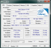
In 2008 I did some research about minimal voltages on differnt Notebook CPUs with rmclock.
![[IMG]](images/storyImages/intelmobilcompare2wv2.jpg)
In 2009 I did some reseach on optimizing thermal compounds for notebooks.
Quiet and Cool. Thermal paste replaced! 38@idle 73@load
And I did some basic research on voltage pinmods.
Core2Duo T5250 (and the same) hardware voltmod(undervolting) !? [1] - RightMark Forums
Now I found additional information on an Intel VID override Circuit.
![[IMG]](images/storyImages/vidoverridecircuit.jpg)
Source: http://download.intel.com/design/chipsets/embedded/323094.pdf
The Solution: The "official" Intel "VID override circuit" may help for an propper pinmod with respect to the signal-IOs
and by the way avoiding the risk of shortcutting the signal drivers.
From Intel-datasheet (i7=Arrandale 32nm):
VID[5:3] and VID[2:0] are bidirectional.
As an input, they are CSC[2:0] and MSID[2:0] respectively.“
Source: download.intel.com/design/processor/datashts/322812.pdf
So these inputs combined with the pinmod can affect the boot-sequence by giving wrong signals to the CPU
(at least at i7-Arrandales, but probably also for Penryns etc.).
CSC[2:0]/VID[5:3] - Current Sense
Configuration bits, for ISENSE gain setting.
This value is latched on the rising edge of
VTTPWRGOOD.
MSID[2:0]/VID[2:0]- Market Segment
Identification is used to indicate the
maximum platform capability to the
processor. A processor will only boot if the
MSID[2:0] pins are strapped to the
appropriate setting (or higher) on the
platform (see “Market Segment Selection
Truth Table for MSID[2:0]” on page 88
for MSID encodings). MSID is used to help
protect the platform by preventing a higher
power processor from booting in a platform
designed for lower power processors.
MSID[2:0] are latched on the rising edge of
VTTPWRGOOD.
Several of the VID signals (VID[5:3]/CSC[2:0] and VID[2:0]/MSID[2:0]) serve a dual
purpose and are sampled during reset. Refer to the signal description table in
Chapter 6 for more information.
Maybe a small circuit can be build for flexible overriding the VID of actual Intel CPUs
e.g. by a combination with a flash EEPROM?
VID-Input to Address lines and Data lines to VID-output. -
Hi guys,
I have a P7350 in my notebook, i would take the t6600 from my brother could i overclock it then? if yes can you discribe how pls? ( sorry for my bad english ) -
If you are thinking of trying to make it go from 11x200mhz=2.2ghz to 11x266mhz=2.9ghz, no this is not possible. It will downclock to 1.6ghz.
-
Though it would work with an nvidia chipset, not many of those around.
Try a pll pin mod:
http://forum.notebookreview.com/har...pll-pinmod-overclocking-methods-examples.html -
my pll isn't support by set fsb and clock gen, i need a pin mod. Can you explain me why it wouldnt work with 266 ? and could anybody help me.
BSEL Mod on a socket P explained with photos
Discussion in 'Hardware Components and Aftermarket Upgrades' started by naton, Jun 16, 2009.