
Hi everyone,
I have updated the first post to show additional examples of successful mods as posted in this thread my NBR members.
Have a nice day...")
-
Can you help me. Will this CPU
INTEL CORE 2 DUO T9550 - 2.66 GHz 6MB 1066 MHZ SLGE4 SOCKET P Works in Acer Aspire 5720G ? for now i`m use T7300 4Mb L2 Fsb 800Mhz.Thank you -
INTEL CORE 2 DUO T9550 - 2.66 GHz 6MB 1066 MHZ SLGE4 SOCKET P will be Works in Acer Aspire 5720G ?
-
can you help me ?
-
Yes, it will work. I JUST did this a few minutes ago to my Toshiba L305! Going from a T7300 won't really gain you much performance I don't think, since the T9550 will also run at 800MHz. Only real benefit will be the cooler temperature since the extra 2MB cache won't be of too much help.
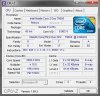
And yes, that voltage is correct! I use ThrottleStop and so far with my preliminary testing, that's my stable Turbo voltage (keep in mind it's running ~500MHz underclocked) My T3400 would do 1.034V but still ran hot compared to this beauty, so happy this mod ended up working.
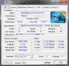
And actually, before I knew 1066MHz would not even power on with my Toshiba (thus knowing I needed to do this mod), I had bought an E8135 which is the iMac equivalent to this T9550. I thought it might be the Mac CPUID that was the problem, but it did the same thing with my T9550. However, after doing the BSEL mod BOTH worked, so here's that screen shot as well
THANKS FOR THIS THREAD! -
You're welcome, and glad that this thread has helped you. I just wanted to add that the T9xxx and T8xxx series run coller than the T7xxx series because they are fabricated using a better/newer fabrication process. I'll update the 1st post to reflect your successful experience. -
Just to make sure, there is no way to get memory running at DDR2-800, is there? I'm assuming that since it didn't change to run at the FSB speed, I'm limited to DDR2-667 unless I am overclocking via PLL? As I've not had any lucky with PLL adjusting on this Toshiba
The correct PLL is in SetFSB, it reads all the speeds correctly, but it doesn't apply :\ And for the record, my DIMMs
are DDR2-800, with a SPD profile and everything
Also as an update on undervolting, I've bottomed it out at 0.9500V and have no instability at 2.1GHz. Oh how nice it would be to have a multiplier pin-mod as well lol
-
Hi mate, what chipset is your L305? I have the GL960 version and I cannot get this mod to work for the life of me. Trying a P8600, the board powers on for a few seconds then powers back off again. I've used the thinnest wire I can find, and I'm deffo using the right pins. :/
My T2370 works fine.
Cheers -
Just want to let you know that this mod is good only if you can up the FSB back to 266MHz afterwards with a sotfware such as setFSB.
If you're in the hunt for buying a new CPU and can't use setFSB, then you're better off buying a T9300 instead. It is a fast, relatively cheap and runs cool. -
Finally got it working! Turned out the alu wire I used actually snapped when the CPU was locked. Used a thinner copper wire instead and it booted first time.
My P8600 still reads as 2.4GHz in the BIOS though. Shouldn't it be 1.8GHz now? Or is the reading wrong? -
you're right it should read/show 1.8GHz.
Can you confirm this reading in Windows using an program like CPU-Z? -
Will do soon as I can, the heatsink is missing its clip so I can't really do much until the one I bought gets here I tried holding it with my hand several times but it keeps overheating haha.
Cheers!
EDIT: Just managed to get into CPU-Z, it is indeed 1.8GHz. Just a reading error then I assume. Cheers -
Has anyone tried to pump up FSb back to 266MHz by desoldering FLSB test pin from motherboard so Montevina cpus could run native speed?
-
Worked perfect!!. Upgraded from a poor T3200 to a P9700!!
Toshiba Satellite Pro L300-1A9: Chipset Intel GL40 - Modded by Arkaknio with a P9700, FSB 1066 -> 800MHz. -
I would like to ask you, if i can use for my toshiba l300 with t2390 (1.86, fsb 533mhz, Ram 1x2GB 533mhz) (GL960 ich8) processor t4400 (2.2ghz 4x200mhz), and what change i will must do. thx very much
-
Hi to all. I'm back
You can remember me and my poor Asus M50Sa. I've made T9300 => X9100 BSEL mod in the past. So, recently I tried to do it again but with P9700 at this time. And I got pre-bios entering freeze. There is info about the CPU, its current speed (2100 MHz), total memory and that's all. I'm a bit frustrated. I've made 2 different successful BSEL modes with 1066 MHz CPUs. And I don't understand why P9700 so differs from X9100 that my BIOS can't load. I've double checked the cpu micro codes (who knows?!), added some new but that gave nothing. So, maybe you have an ideas?
-
OMG, I did the BSEL mod with Intel Core 2 Duo P9700 CPU. But I did it in a very tricky way:
1. I've inserted the CPU microcode for new CPU.
2. I've flashed new BIOS with that microcode inside.
3. I've done the BSEL mod as usual.
4. And... with new BIOS my M50Sa just have freezed at the start-up - no action after showing total memory. And I couldn't launch the BIOS setup.
5. So, after a few weeks of nothing I tried to use an Asus built-in alternative start-up launcher for BIOS - aka Speed-blah-blah (don't remember the actual name). I've just pressed the dedicated button on the surface of the laptop (not the power one, different).
6. And I got the exception, which let me to launch the Windows.
Now I can work with my new P9700 but there are 2 further exceptions: OS thinks that CPU is working with 1,05 GHz speed and the total memory is 3Gb (instead of 8Gb installed).
Currently I don't know how to solve it. It seems that this goes from badbrewed Asus's BIOS... -
I did this pin mod on a P8600 on my Lenovo N500 (still not sure if its a GM45 or GL40, though i-nex in ubuntu says GM45) anyway, it worked well. I also later tried it on a dirt cheap $10 E8335 from a iMac and it also worked well. I'm currently running the E8335 @ 2GHz instead of the stock 2.66GHz. I have access to a cheap ($30) Q9000, but I'm not sure it it would be worth it in terms of performance gain. Any opinions on whether a Q9000 would work and would be a worthwhile upgrade from the E8335? I'm guessing it would run about 1.5GHz, right? So a 2GHz dual vs a 1.5Ghz quad... I'd love to bump the FSB back up, but Lenovo has this bios locked up and I'm running linux and doing such in Linux involves compiling kernel modules and some special dancing or something and I've been to lazy to do that as of yet
Attached Files:
-
-
is there a way to get SETfsb to work on a Toshiba l305 on GL40 chipset with an RTM875T 606? it already supports the same PLL for an HP, however it does not give that PLL as an option in the drop menu when i run it on the Toshiba L305-S5971
-
Because RTM875T 606 is available in shareware version not freeware. Check here: http://forum.notebookreview.com/hardware-components-aftermarket-upgrades/429717-rtm875t-606-info-gathering-ocing.html. Basically You can still overclock using nearby Realtek PLL from SetFsb drop menu, but You have to check if TME is enable on Your machine and if is that's mean soldering work on PLL to disable it. And there might be case as well of changing source clock for SRS PLL to avoid locking and crashing laptop.
-
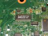
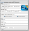
is that a good enough image to tell?
RTM875T-606 datasheet & application note - Datasheet Archive
http://forum.notebookreview.com/har...clocking-methods-examples-23.html#post5457881
is there enough information here to tell if it's locked? if it is locked is there enough info to figure which pin needs to jumped to ground?
EDIT: http://forum.notebookreview.com/har.../429717-rtm875t-606-info-gathering-ocing.html -
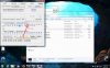
RTM875T 606 is pin and it looks like byte compatible with ICS9LPRS365. You have rectangular version then it's like ICS9LPRS365BGLFT: ICS9LPRS365BGLFT pdf, ICS9LPRS365BGLFT description, ICS9LPRS365BGLFT datasheets, ICS9LPRS365BGLFT view ::: ALLDATASHEET :::. To check TME status run setfsb diagnosis and check Byte9 Bit6 readout. If it's 0 then overclock is allowed, if 1 then You have to ground pin 4 to unlock it. From the photos it looks like trace from pin 4 is going into motherboard so You will have to grab multimeter and find where this connection pop out.
cdoublejj likes this. -
i took pictures of setfsb and what i think might be bit6, i just assumed bit 6 correlates with the number 6, so i selected the fields under number 6, RTM875T-606-L03-S5917 - Imgur
why do we need the data sheet for the other PLL when we have the data sheet for the RTM875T 606?
and if it helps i can set it up for remote control and PM the PIN number for teamviewer so someone who CAN read hexdeciamal can take look in person.
I'm only in such a hury to get this done because it's a charitable gift.
http://www.overclock.net/t/1496498/build-log-charity-build-silver-hodgepodge
EDIT: what would happen if grounded it out even though i CAN over clock it? would it then lock it?
EDIT: if i set SETfsb to "ICS9LPRS365" and hit get fsb it says "PLL ID error" -
how do you which bit is bit 6?
RTM875T-606-L03-S5917 - Imgur -
Ok. I understand that You want permanently overclock this Toshiba, with now T5800 installed. The best way would be doing so called FSx hardware pin mod to force 266MHz FSB instead 200MHz, which would boost cpu frequency to 2660MHz from stock 2000MHz. First thing I don't really know if T5800 will be stable at that speed or if it will even boot without overvoltage. Not mention that 667MHz RAM after this mod will be operating at 887MHzz frequency. That's why I would propose to overclock it with SetFsb first to check if the system will be stable at that speed and if not to find what cause the instability: memory or to low cpu voltage. As a side note: I don't know how much You paid for T5800 but much better choice would have been Penryn based 45nm T6500 if it could been find for similar price. But back on topic. To overclock with SetFsb You Have to check TME status of PLL. Open program and choose from the list of clock generators one of RTM875(6) or Pll diagnosis. I think that all of them should give You right readings about TME. Here You have example where and how to read TME status: http://img837.imageshack.us/img837/7788/smps.png. I provided datasheet for ICS9LPRS365BGLFT because from it we know which registers are showing TME status,it is Byte 9 Bit 6. Like I said before this RTM...606 and ICS..365 are interchangeable, pin compatible and we assume there registers asswell. What You provide about RTM...606 are not datasheet of ic itself but schematics of some motherboards using this PLL. Back to Your case it will be that same,You have to select Byte 9 and in field "Bin" will be seven digits. First from left is Bit 7, second Bit 6 and so on.
Off course TME might be disable well, then You are lucky. If TME is enable You will have to ground pin 4 through resistor eg. few kohms to unlock it and allow overclock. Like I said: from photo it looks like trace from this pin is going into motherboard. You could solder directly to the pin or trace but it would be difficult because there are so small. Better option is to find where it leads to, probably to a resistor, and solder wire to this resistor. What I see, there are few "schools" how to ground TME:
1.Cutting trace coming from the pin or pin itself and soldering it through few kOhms resistor to the ground
2. Cutting trace behind the first resistor coming from the pin cause this resistor is usually few kOhm anyway, or lifting one side of the resistor by desoldering and soldering it kinda one side in the air and solderind grounding wire to this side
3. Soldering grounding wire to the other side of resistor - I did that and it worked for me, it looks for me as the easiest way to do this
If the TME would be disable You could start finding the limit of the cpu and memory. To overclock You would have to choose one of the RTM875(6) PLL's, depends which one would give You good readings of FSB bus. If You would establish that and knew what is needed to run cpu at 266MHz bus speed You could perform FSx pin mod.
T5800 is on 200MHz FSB, to boost it to 266MHz, pin FSB need to be pulled down making it logical 0. FSB is on pin 57. Grounding this pin through few kOhms should do the trick.
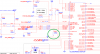
I'm not sure but I might find actual schematics for Your Toshiba, there are few clues which lead me to believe that those are right ones. It might help with mods if it's actually it: http://kythuatphancung.vn/uploads/download/39217_INVENTEC_Sacramento_10,_Phoenix_10_%28Build_ES,_REV_X01,_2007-12-12%29.pdf.
Oh yaah I forgot to attach Your photo with markings of TME and FSB pins. Here it is:
 cdoublejj likes this.
 -
Actually My goal is to use SETfsb. I don't really believe i FSB mods because the jump is far to big for ram and OC to handle. It's easier to do a PLL mod and
make setFSB start with windows.
I have more pictures of the L305-S5917 Toshiba mobo though i doubt they will help, https://imgur.com/a/0Y6jN
Thank for the help with setFSB, if i am NOT mistaken it is a 1 and designates a locked PLL and does need PLL mod.
Just like before i have posted a screenshot.
I hope it's matter of grounding it out.
I will disassemble the laptop and take more pictures and i can use a digital mutli meter to try read the resistance on the pin.
here screen shot of setfsb available "TRM8xxxxx" PLLs,
-
Yep, Byte 9 Bit 6 =1, TME enable - no oc. About avaiable PLL, RTM875T-587 was used by someone in thread about RTM...606 and worked fine. If not just simply choose next one. Schematics posted by me seems to be right one for this laptop. So try to locate resistor R780, it might be on the other side of the mobo then PLL. Actually it should be rather empty place for resistor. But being honest I don't know if it is market.
 cdoublejj likes this.
 -
http://forum.notebookreview.com/att...l960-gl40-useful-info-pll-modders-ics-rtm.png
PIN 4 PCI2-TME.....how do i know which pin on the chip is pin 4. the PNG does not show the marker that helps me orient the chip.
as usually more pictures.
EDIT: i see the "U7" maybe that will help!
EDIT:
This ^^^ pin, reads ".556" - ".555" when i set my DMM to 2k
pic...
Here ^^^ i set it to 20K -
i guess just try pin 4 to ground and see if setfsb changes? or would that maybe start a fire?
-
I already mark You pin 4 on my previous photo. You have kind of small dot on the upper left corner off PLL which indicate pin 1.
View attachment 113688
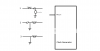
If You want find where pin 4 leads to You have to set multimeter to this:
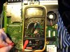
When You will connect, touch the probes You will hear beep indicating connection. Now You just have to put one probe on pin 4 and touch with the other one any solder joints, resistors in hope to hear continuously beep which will mean that there is connection between pin 4 and probed place.cdoublejj likes this. -
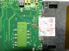
wow, that PNG you link is WAAAYYYYY off then. of course it was said earlier they are not necessarily representative of the actual pins. HOWEVER!!!! The pin you proposed as pin, i was not able to track down to ground but, instead it connects to bunch of other pins on the PLL. i start swiping across the pins and the buzzer lights of pretty good on several pins. do it directly from pin 4 and none of them beep except for the traces pictured below.
i was able to trace your proposed pin 4 to a resistor and measured it.
https://imgur.com/a/ArFOD
YOU MUST zoom in on these pictures to see the lines i drew.
EDIT: doesn't beep if there is a resistor in the way but, will give a number read out. (yes on continuity setting)
the pin i initially thought was pin 4, initially looks to be a dead end. -
I think that empty space for resistor on Your photo correspond with schematics R780 which was described "open", which I assume, means that this resistor was never soldered there. If You look on the schematics You see that pin 4 is connected asswell through 10k resistor to the 3.3V which pull this pin up. Putting resistor in empty space of R780 should pull it down and do the trick. Can You check then if other side of this empty space for resistor is a ground?
Sorrry. My mistake. Because I just saw Your second photo from the PLL side of the mobo. We need to clarify that. Which place give You readings. I mean continuously beep. It has to be like that. Sometimes it wiil be like some buzz at the beginning and fading but it's not good one. It has to clear beep all the time.cdoublejj likes this. -
defintley, 1 continuous beep as long as they touch. you don't have to worry about that.
YOU GENIUS!!!
the solder pad you circled where the resistor should go IS GROUND!!! 1 solid long beep.
what resistor do i need? i have POTs! 5k, 50k and 100k...if I remember correctly. -
If on the other side connected to 3.3V is 10k then I think 10K to the ground might be ok. It might be less asswell because levels of voltage to be read as the logic 0 don't have to be exactly 0V too. If I remember correctly for a FSx readings it's eg. 0-0.3V will give logic 0. Maybe 5k will be ok.
cdoublejj likes this. -
should i solder the pot strait from the pin to ground or use the solder pads? my 5k pots read 5.05 on 20k setting on DMM. gonna measure my 50k. can' i use a 5 can turn it up to 10k ohm?
if the mod does not work should i try setting resistance to 0 or give up/leave it be?
okay i se the 100k pot to 10.05 on the "20K" setting on the DMM, under the assumption is my 5k pot is really 5k and it read 5.05 on "20K" on the DMM then double that should 10k.... cause i'm not very good at under standing the DMM settings sometimes. -
Solder pads will be much easier to solder. You have there a some kind of solder ball next to pad asswell, then it' perfect place to do this.
-
Solder pads will be much easier to solder. You have there a dome kind of solder ball next to pad asswell, then it' perfect place to do this. Maybe You can solder 10k first and see what it does.
cdoublejj likes this. -
uughhh.... could be better but, it's so tiny the slightest tremor from hand causes problems. I'm going with the 100k pot @ 10k because i adjust it down to 5k or lower or higher.
I can run the wires else where so i can easily adjust the pot.
EDIT:
cleaning the joint.
EDIT:
should have checked continuity before i put back together but, since the POT is the HDD bay i still can! maybe 10k was not enough or too much? -
set 100k pot to 10k but, installed it reads a max of 8k, i'm gonna see if i can get up higher then maybe try 0 resistance, then if that fails re calibrate it and check the solder connection continuity.
other wise it's still locked.
EDIT
YES!!!!!
Yeah. It even crashed when i tried to apply a 7mhz OC to the FSB with RTM870t-691. Need to find a compat PLL on setfsb. I think i will try "ICS9LPRS365" next.
OH YEAH! I had to set it "0" ohms, or straight jump if you will. it needed not more resistance but, just a connection to ground. having known that i could have just bridged the 2 solder pads. at least this way i can lock the PLL if need be for some odd reason.
HHHMMMM, might have hit a wall. it seem i'm struggling to find a suitable PLL in setfsb.
EDIT:
http://forum.notebookreview.com/har.../429717-rtm875t-606-info-gathering-ocing.html
it would seem i need to identify "00h"
found 00h and i need to change bit "2" to a (1)., i assume the first digit, 0 means nothing. which would mean the 3rd digit from the left but, that didn't do any thing so.....
if i change it from 010 to 011 it makes no difference.
EDIT: it maakes no visible difference, while it reads 266mhx buss i can manually set it and over clock, despite skewed readings.
how do i get it boot up that way? do the settings stick?
edit, i rebooted and and the settings that made RTM875t-587 work stuck. so now perhaps it's matter of making a shortcut for for start up programs.
EDIT:
http://www.overclock.net/t/927882/setfsb-auto-startup#post_12193325
alright but, i need a way to manually set second slider to 760 as shown here,
http://forum.notebookreview.com/att...28-rtm875t-606-info-gathering-ocing-demo2.jpg
EDIT:
-
Try to use RTM875T-587. ICS9LPRS365 will not work, it will give You "PLL byte error". It has to be clock from the same vendor. Is RTM875T-587 shows You right values of FSB, memory, pci? And what's happening when You try to change FSB, like 5MHz up?
cdoublejj likes this. -
I have to modify a "bit 2" for it to work but, it does over clock however it's REALLY weird, at first it reads the clocks as 266mhz and the PCIe as -7 mhz. i have to manually slide the PCIe to 760 then it calculates the PCIe as 2400mhz then as soon as i hit setfsb the PCIe starts reading correctly @ 100mhz. Since it reads the FSB as 266mhz i have to manually scale it back 200mhz and then start from there. it seems fine 215mhz FSB but, then craps it's self if i go any higher.
also when it is over clocked GPU-Z reads the in the GMA as still 475mhz. i thought it was supposed to go up with the FSB? i wonder if there is a way to do some trickery with soldering/jumper mods to make it run at the full 533mhz. -
What about next clock from the list RTM876-660 and RTM876-665? When You say "modify a "bit 2"" You mean changing Bit 2 in Byte 0 from 0 to 1, yes?
cdoublejj likes this. -
http://forum.notebookreview.com/har.../429717-rtm875t-606-info-gathering-ocing.html
scroll down to where it says, "I won't care if you KILL your NoteBook, Burn your House Down, or knock up your Dog, with anything you read here. It's not on me, it's yours, you did it, deal with it."
those are the instructions i followed. after than applying clocks didn't inst a crash the machine and CPU-Z actually confirmed the OC.
I might be able to "fraps" it at some point, so you can SEE what it's doing. -
what is the difference between shareware and freeware... actually never mind, if i get the pay for version should it show up?
EDIT: i'm going to try version 2.3.178 -
2.3.178 has the correct PLL and could used to OC at boot.
-
hi how i can downclock a socket p cpu with bsel mod
-
Could someone upload the pictures again please, the thread is otherwise useless. I can't find how to downgrade fsb from 1066 to 800 with BSEL mod nowhere. Everybody talking just about ovewrclocking. Thanks much.
-
Here You have some examples how to do this, first schematic: http://imagizer.imageshack.us/a/img812/3903/pinsocknwires.png and actual pfotos of mod: https://fbcdn-sphotos-d-a.akamaihd.net/hphotos-ak-frc1/906116_448213211963119_1522309784_o.jpg, http://imagizer.imageshack.us/a/img59/1198/socketnwires.jpg. In the last photo important is only top wire, the bottom is for vid mod - changing the voltage.
-
TY mate. Just one question. It is for socket P and 1066 to 800Mhz? Coz I destroyed one laptop already with modded bios. I can't afford to break this one. If u sure the I'll do it. Just be sure pls. And thanks very much
-
Yes it's for socket P, but it doesn't matter actually, because location of BSEL and surrounding them Vcc and Vss pins are that same for socket M and P.
FSB downclock mod on the intel GL960 and GL40 --- useful info for PLL Modders
Discussion in 'Hardware Components and Aftermarket Upgrades' started by naton, Aug 21, 2011.


