
i manage to clock my FSB to about 255 yielding 2.8Ghz yesterday without the speedstep tweak enable but it BSOD after about 3 min and after i reboot, my TME is locked again
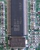
this is the stable clock i tested without crashing on my first try before i ramp up the FSB even more(this is with IDA Enabled)
![[IMG]](images/storyImages/65295715.png)
this is what it looks like when i can overclock my FSB
![[IMG]](images/storyImages/84276292.png)
and now it is locked again and i am not sure what is going on
![[IMG]](images/storyImages/123123nz.png)
my theory is that the resistor becomes looses contact or worse it might be more complex than what i have imagined
im very sorry for the quality of the photos but my Logitech C260 won't focus on the image
what i did was put my resistor on the other leg of the transistor pointing to the PIN 4 and i put the other end of it in a screw hole and screw it in
i am not sure if am even doing the right thing
-
-
The method you are using is a pull-down resistor and must be attached on the resistor leg side that connects to the PLL pin 4. The resistor needs to be soldered to the resistor leg OR any solderable point along the track between it and the PLL pin 4 to ensure a consistent and reliable electrical connection. Sometimes there are via solder blobs on the track which can be used.
The screwhole side just needs to make contact with the screw and post to provide a GND point which it will. -
just a quick update:
i opened up my laptop and for sure the resistor is not touching the resistor for PIN4
i already fixed that and booted on windows and checked setfsb if it is locked or not
now it is TME-Unlocked
however i observed that if i set my FSB for example to 230, it would BSOD but if i do it in increments (starting at .05 to 30) it would not BSOD
i am now running at 240 and i am checking if it is prime95 stable but i observed something very weird.
the multiplier will drop to x4.0(960Mhz) wile running prime95 randomly
![[IMG]](images/storyImages/asdq.png)
![[IMG]](images/storyImages/qwelt.png)
also my ram is only running at 400 according to cpu-z
![[IMG]](images/storyImages/123unw.png)
i can confirm that my computer is not overheating because it is running very cool while at 100% load at prime95 right now at 240FSB -
[ double post ]
-
240/200*333=400Mhz, so yes, your RAM is running 400Mhz, yet has 5-5-5-18 timings set for 333Mhz. The x4 might be SuperLFM kicking in during idle times. You can prevent that by installing Throttlestop. Also recommend install Throttlestop to control the voltage and CPU divider to use, as well as do dual-IDA.
Refer to my previous post on changing your RAM's 333Mhz SPDTable entry to have CAS=6, overvolting the CPU and changing X3100 settings if you want to try to overclock further.
If you can setup a stable dual-IDA overclock at 240Mhz@x12 you'd be running 2.88Ghz. A nice overclock over the T7500's stock 2.2Ghz. -
im about to test GTA IV and it GOT LOOSE AGAIN!!!
this is the 4th time it happened today
i got a super glue in hand right now and i want to glue this this for good
is it safe to use super glue? -
Suggest take your systemboard or dismantled notebook to a mobile phone repair shop and pay them $5 to solder in that TME-unlock resistor. That will then be a proper electrical connection. It will take them 2mins to do. Superglue might or might not work. I wouldn't use it as it's not guaranteed to form a 100% electrically reliable link. The stuff is a pain to remove if it doesn't work.
-
there is a problem with the spdtool
it give me errors
![[IMG]](images/storyImages/54469992.png)
![[IMG]](images/storyImages/27346532.png)
-
Try writing either RAM module with CAS=6. The chipset will read both modules on bootup and use the slowest RAM timing it finds so only need to flash one of them. If there is a problem with the SPDTool software itself then can try the trial version of Thaiphoon Burner. The trial version I tried worked great with XP but has some problems with Win7. Latest version claims Win7 compatibility.
-
the spdtool is not working for me
i will try to get my hands on Thaiphoon Burner
right now this is my absolute maximum stable overclock using 2.5v on prime 95
![[IMG]](images/storyImages/70015637.png)
if i go higher than that, it would instantly lock up my computer or i would get BSOD
i suspect the ram is at its limits right now so i need to find a way to increase the timings for more breathing room
![[IMG]](images/storyImages/74026010.png)
i also tried upping the PCI-E clocks but it would instantly make my computer lockup or i would get BSOD(i do it by 1 increments)
i also discover that to prevent my computer from locking up or getting BSOD, i should only increase my FSB for about 4 increments each adjust
sadly the DUAL IDA trick is not working for me anymore
if i choose 12x. it would instantly lockup my computer. also if i uncheck the SuperLFM. it would instantly lockup my computer
it is now not dropping to x4 while doing prime95. what i did was select 1.25v then check iest then select 11x multiplier then turn on then uncheck iest and it is now locked at 11x and it is not dropping to 4x anymore while doing prime 95 -
Ensure you've put your CPU voltage to the highest available before starting dual-IDA. If the system freezes then the T7500 just can't handle running at the overclocked BCLK you've set.
A T8100 would be more likely able to handle the overclock due to it's 45nm tech with smaller and better internal cache. ebay shows T8100 and T7500 are the same price so changeover costs would be minimal. The T8100 being more suitable for your overclocking purposes. -
i found a way to make the DUAL IDA trick work on me
what i did was Run throttlestep step first and do the DUAL IDA Trick
if i do the setfsb first. it would result in my computer lockup
right now the maximum overclock i manage is 245 + 12x and it is stable on games but it would crash on Prime95
so i lowered it to 241 + 21x and it is running very stable on Prime95
![[IMG]](images/storyImages/123li.png)
![[IMG]](images/storyImages/345w.png)
right now i currently settled to 240 + 12x and it is running very stable and very cool especially at games
i still haven't found a successful way to change the SPD on my RAM. the only last resort i am thinking now is to use WinXP and try if SPDTool would work on it but i don't have WinXP in hand right now so it would take time if that is the only option
as for the T8100. im having a hardtime justifying if i should get that chip or not
if i can clock T8100 for atleast a minimum of 3.2Ghz on my computer, i would seriously consider getting it. published results of an overclocked T8100 would be nice and an overclock 3.2Ghz+ would be more than welcome
-
Well I couldn't stop myself, went for a pinmod today. First tried the fsla pinmod, no POST. Then tried the TME pinmod (followed what nando4 did with his HP 2530P). byte 9 has gone from 65 to 25. I am trying to find the registers that control the FSB (hard without a datasheet).
-
Hi all
i have a doubt on solder the pin 57 to the ground can i solder the wire from the point 1 to the ground, like image (because it hasn't a resistor) or i must disconnect the pin 57 from the board and solder a wire from the pin to the ground.
-
Yes I think that should work.
But to be safe, I would use a resistor when you connect point 1 to ground. -
What kind a resistor may i use, i know that someone on the forum used a 33ohm!! 10k seems too small!! any idea?
-
A larger resistor is preferred for your application as it just acts as a very low power protector against short circuiting. P=V^2/R
-
Well, thats interesting about the power saving mode on x3100 IGP allowing for higher overclocking. I wonder about pci-e and sata power saving modes?
What were you trying to do moral hazard, couldn't you find the registers eventually with setpll trial and error? -
If you're talking about the nb500, I was able to find one register that changed the frequency. Only problem is that the system locks up 99% of the time when I change that register.
If this netbook had a restart button then I could change the register, restart and have the frequency I want. But I can't restart (only fully turn off and turn back on, which resets the PLL registers)
I have been thinking of wiring up the FSlB pin to the power button. Since that pin is sampled when the system is turned on, it would look grounded. But then I would let go of the power button and the pin would get it's normal USB clock signal and the system should POST. At least that's the plan. -
SetPLL has been updated.
revision.txt
Code:1.0e (3-14-11) BUG FIX: to be able to run setpll by giving it's full path, eg: c:\setpll\setpll ics.. so resume-setpll.vbs will now work. BUG FIX: delay was off by 1 second. BUG FIX: ics9lprs387bklf to allow pci-e clock changes. Added -read param to read PLL data and initialise myPLL.lut Set default delay parameter when specifying a list of BCLKs to 1 second. Added comments explaining PLL config registers to ics9lprs387/397.LUT Fixed some typos and revised in setpll.txt Included DavyGT's latest m11xR2.lut up to 197Mhz BCLK. -
ok the resistor is like this View attachment Resistor.bmp . But don't know the "power" ohm's or K that may use. i now P is Power , V is voltage, but i don't know out to measure them on the chip. I'm a noob on eletronics, sorry my question!!!
-
Hello guys again.
I recently sold my fsc since I couldn't add more than 4gb mem and I found a used Y550 which is a great laptop except from it pll. It got a SLG8SP556V.
On a russian forum (thanks to google translations) I found a guy who has done a breakdown and here is a photo of my pll and its surrounding components.
In the same album he has a pll pinmod to jump from BCLK 200 --> 266. The problem is that I have to completely open my laptop.
From the maintanance lid I can't see any further than the left side of the sticker.
Any solution without a breakdown? (For example If I can disconnect a resistor and make a pinmod on the socket)
He also claimed that he contacted abbo and abbo told him no way to add his pll.
I have also read that there is no bios restriction for a quad core cpu only power restriction. So, does anybody know what changes do I need to make to make my pm 45 mobo accept one?
the bigger the resistor the better. You can measure using the colours on the skin.
Thanks in advance. -
You need to look at the colored bands on those resistors and compare them to a chart like this one to find the resistance value.
-
ok, i now, thanks, but how many ohm's may i use, What resistance power i use, to connect to pin 57?
-
An 1K (Ohm) would be ok. But its better to hear for a more experienced member like nando4 or moral hazard before proceeding.
-
I would agreee with 1k, most of the time when people do PLL pinmods I see them use 10K resistors.
@timohour, the alienware M11x R1 uses the same PLL as your Y550. You can see something interesting here:
http://forum.notebookreview.com/ali...-m11x-r1-slg-hardmod-only-43.html#post7235330
A quad core CPU may work. I think if your bios supports it, the notebook should startup fine but you will only get 2 cores working in windows unless you make some hardware changes. That could involve a CPU pinmod. Was talked about in this thread:
http://forum.notebookreview.com/gat...re-q9100-gateway-fx-p7801u-4.html#post7052146 -
Thanks for the quick reply. I am gonna search further, but I don't see other solution than the pinmod.
for the quad.
what do you mean about the bios support? Is it really necessary, cause Y550 never got a quad. (only Y550p which got i7-720qm) -
Actually I'm not sure about that. I would have expected some problems if there was no bios support.
At least if you have an AMI or phoenix bios it should be easy to add bios support for a quad core CPU if you need to. -
Thanks for the tip. It does carry a Phoenix bios (made maybe by macgyver ) so maybe its time to try. As I saw in the Gateway forum, nobody found a way out to this. Am I right?
Also after reading the M11x I found out that only a pinmod is available. Since I don't want to open my laptop completely, I will have to abandon my project on pinmodding. Thanks for the reply. -
I've seen 33ohm(as per Nand0 instructions). I've tried it with both 33 and 100ohm 1/8 watt resistors and it worked. My system (HDX 9000) just has issues with FSB overclock in general.
I suppose the higher the better since the goal is to pull down to logical 0. -
Thanks all for the reply
I'll try to overclock my system from 200 to 266, but first i must change the memory settings (Samsung M4 70T5663QZ3-CE6 667mhz) , then i must increase the cpu voltage (vid4+vss) and finally i must solder a 1k resistance from the pin 57 to ground. (SETFSB not possible).
My memory settings must be 667mhz with 800mhz cas latency settings or may i use 400mhz with 667mhz cas latency settings?
The memory speed depends on the system or depends on the memory, if i put a 800mhz memory on my computer without overclock, the memory speed change to 800mhz or will remain 667mhz? -
Its not mandatory to do this but its for the better of your ram. If your ram runs on 667 it will overclock to 887MHz so the 800 cl settings would be better.
That really depends on the system and the memory.
if you have a gm965 or pm965 (santa rosa) or an earlier chipset with core 2 duo (945) you are limited to 667MHz. Some late santarosa chipset (named revised) could accept up to 8GB 800mhz ddr2 ram but this is limited to a small number of laptops (you have to check by your model).
PM45 and GM45 (Monteviva) would accept 8GB ddr2 @800 and some of them a very rare ddr2 sodimm memory module with 1066MHz.
I personally tried to use 667MHz memory on a gm965 motherboard but the driver of my gpu kept rebooting so I swaped one of my memories with a 533MHz chip and my memories worked @ 709 4-4-4-12 timings with no problems for over 6 months.
You could also try running your memories @ stock timings and only if you face problems flash their spedds to 800 timings.
If you do have problem recognising your chipset download cpu-z or give me your model No and I can maybe help you.
edit: from your previous post I checked that you have a A300 which carry an pm965 chipset. Crucial.com says that pc2 6400 modules will be combatible. However since it says the same for another gm965 I tested they won't run @ 800 only 667MHz, and since nobody else using this model (as far as I searched) seems to actually worked @ 800mhz, you are stuck at 667. -
Trying TME-Unlock on the HDX Dragon again. This time I used a 1K ohm resistor and the remote control works. When I used 33ohm and 100ohm, the remote ceased to function.
This is a good news so far. Now I'm working with M. Abo to get a proper entry for my PLL ICS 9LPRS501PGLF. -
Hello,
After a long time of searching the right chip, i've found it.
My ppl is "ICS9LPRS365BGLF" ---> "Get FSB" detect the right clock: 266.7/533.3/100.0/33.3
My CPU is a P8700 @2,53Ghz
Laptop: LG P310 Melara
Now i've tried to set the FSB from 266 to 270 with setfsb but this hadn't got any effect. Unfortuantely i don't know, if i have to set some other values on "Diagnostics" or "creator".
Do you have any tipps for me? -
You have to TME unlock the PLL first for it to work. See first post on how.
-
I downloaded and quoted the two processor pinouts (core 2 quad and core 2 duo) and I found out that they have several differences.
pin------quad-----------duo
B2---BPM2[2]#-------RSVD--->(Common Clock Input/Output)
D3---TDO_M----------RSVD--->(Open Drain Output)
D22--GTLREF_2------RSVD--->(Power/other)
F6----TDI_M----------RSVD--->(CMOS Input)
F8-GTLREF_CONTROL-VSS---->(CMOS Input/Output)
M4---BPM2[1]#------RSVD--->(Common Clock Input)
N5---BPM2[0]#------RSVD--->(Common Clock Input/Output)
V3--THRMDC_2------RSVD--->(Power/other)
AA7---BR1#----------VCC---->(Common Clock Input/Output)
AA8---RSVD----------VSS---->Reserved
AC8---RSVD----------VSS
AE8--BPM_2[3]#----VSS--->(Common Clock Input/Output)
That the differences and next to them the definitions for the quad core.
Anybody who have an idea what are all these would help.
Thanks -
setpll 1.0f released with quite a few additions and enhancements as per history.txt entry below:
Code:1.0f (4-4-11) -------------- NEW: Additional OC related utilities included. automated\ - Folder of scripts to do automated overclock. setIGP - to increase/decrease Core Render Clock on GM950/X3100 GMAboost - a GMABooster clone to do a netbook GMA950 overclock HPfan - to save/load HP Elitebook fan profiles DSDT\ - iasl+asl to create a custom DSDT override for fan control devset - (devcon) to optionally enable/disable devices NEW: setPLL -report now sets 'cpu' and 'cpu_bclk' DOS variable for your own batch file queries. Also does this after setting a BCLK. NEW: '-read' now dumps [READBACK_BYTE (0xC)] bytes as is set on PLL NEW: '-read [READBACK_bytes]' sets that PLL register then does '-read' NEW: Added half-multiplier support to chkcpu32-based cpu.bat NEW: start_delay parameter in resume-setPLL.vbs NEW: no longer have brief r-w minimized startup flash screen. FIX: PLL smbus read/write command endbyte was off by one byte FIX: pcie line fixed in myPLL.lut template creation. FIX: more accurate cpu_bclk frequency reporting FIX: removed last delay after setting the final BCLK in a list UPDATE: Added 127,129,131,133 pci-e clocks to ics9lprs387/397 UPDATE: ics9lprs501pglf.lut revised and tested on HDX9000. UDPATE: revised commandline usage output. UPDATE: cpuz 1.56 -> cpu-z 1.57. UPDATE: r-w everything 1.4.9.1->1.4.9.10. New /command /stdout parms. -
Could this be the M11x R2 PLL? It has ICS and a 14.3mhz crystal on it yet Google returns nothing for "ICS VS318BL".
![[IMG]](images/storyImages/img07911.jpg)
-
Hello, my first post to this forum
I managed to make TME unlock mod to Dell xps m1530. This one has 8600gt graphics and the clockchip is SL28541AQC. There is also another motherboard version with ICS 9LPRS365BKL clockchip. TME mod allowed me to use setfsb. After I verified that the 266mhz bus clock was stable I made FSLx mod connecting FSB via 10k resistor to ground. All mods can be done without opening the computer. I post pictures with more details later.
Here is a cpu-z validation for max stable clock with this current processor.
CPU-Z Validator 3.1
Here are some pictures explaining more about the mods. Resistors are located just under the wlan slot.
![[IMG]](images/storyImages/25a3qz4.png)
![[IMG]](images/storyImages/10dv9s7.png)
-
I have been trying to get some kind of pll/ TME unlock mod working on my HP 2730p (it has the SLG8SP553V PLL chip), and while I can find information relevant to other pll chips, I have yet to find something saying from which pin I have to solder a resistor to (but of course the other end should be grounded)... is it even possible on this pll chip? I am assuming yes, but I can't figure it out...
A picture of my chip :
![[IMG]](images/storyImages/5608628782_86e9e832fb_b.jpg)
This looks like the closest thing to my chips data sheet Powered by Google Docs (not a exact match as mine has the "V" at the end -though I don't know what significance that is)
So I am assuming I should solder to the surface mount resistor that connects to the 5th pin up from the bottom, on the left side (R856 that would be, correct? as it is labeled as "PCI_2" in the chip's data sheet... or am I looking for a different pinout? I saw in some other chip data sheets that a pin labeled as "PCI_2/TME" , and not just "PCI_2")
Then the question is (assuming everything is working after a hardware mod) what software do I use? from the sound of it I should use SetPLL, and then which pll version do I select from that software... I have not done this before, so I don't know what to do to get it working
Well, any help on which pin to solder to, or whatever other steps I have to take, would be greatly greatly appreciated (I have been trying for a bit now, with no success...) -
@Agent 9 your SLG8SP553 PLL datasheet doesn't indicate any programmable registers so not sure if a TME-unlock + setPLL is even possible. You'd be experimenting to try to find out.
What is possible is a FSLx PLL pinmod like discussed at http://forum.notebookreview.com/ali...-m11x-r1-slg-hardmod-only-11.html#post7059466 . 300Mhz would boot up OK but requires wiring a LOGIC 1 to FS_C, FS_B and FS_A. I doubt 333Mhz would boot but you could try by wiring a LOGIC 1 to FS_C. Your dual-IDA L9400 would be overclocked to:
300x8=2.40Ghz
333x8=2.66Ghz
I don't see any pci-e clock control either, in case you were looking to improve your DIY ViDock performance.
It's a shame you got the SLG PLL on your 2730P systemboard rather than the ICS one which has been successully TME-unlock PLL pinmodded here. -
Thanks nando4... so that means my processor would be stuck at the 300Mhz bus speed if I were to do that mod? (so it wouldn't clock down to 266 or below when idling low, or would that still work properly?) I like the Dual IDA mod I have going because it is software controlled, and I can still put it in battery saving mode when I need it, and losing that efficiency for a slightly better processor speed isn't worth it to me [my priority is portability, and longevity on battery power, over raw speed]
I was hoping to be able to OC my pci-e bus so I could eek a bit more performance out of my DIY ViDock, but I guess I can't (it performs pretty well -a GTX 460, PE4L adapter, and the Corsair 430Watt PSU you recommended- I have a small thread going on TPCR -the sister site to NBR- where you can see the benchmarks so far
DIY ViDock on Tablet PC's: experiences, benchmarks, setup, ect... ... though it needs to be updated)
-
A 266->300Mhz FSLx PLL pinmod would see you running a 300Mhz BCLK rather than 266Mhz. So your lowest multiplier would be 300x6=1.8Ghz. I'm running my L9400 at [email protected] (lowest) on DC, so you'd be able to do run 1.8Ghz without any problems and maintain your great battery life.
The 2.4Ghz AC dual-IDA overclock you'd get from this would also see you getting faster DIY VIDock performance since x1.Opt does CPU compression. Of course, a pci-e overclock would help further but I can't see your PLL being software programmable to allow it.
Great work on the TPCR DIY ViDock thread
-
ok, so then the processor would still be capable of throttling some (which is good) I think it would be worth a try then... only issue now is, how exactly do I do the mod? (so its pins 20, 2, and 7 for the FS_A/B/C respectively... but then what is the "LOGIC 1" you mentioned, and do I just connect all 4 of them to one another? (so they are all electrically tied together, or is it a different combination like A to B and C to Logic?)
I created the thread on TPCR because graphics power is the one big thing all Tablet PC's lack, and few people know about the DIY ViDovk, or don't know it can work with a Tablet PC; but I was sure to link some of your best posts so they can get the info they need (your in depth details, and guides are really great)
Thanks for your help with it all
-
Very confused with these instructions. I can sorta understand them, but before I cut anything on my laptop i'd rather be sure of what to do.
Are the supplied pll files all ready to use? Do I just load that and set the shortcut in the startup forlder and be all ready, running at 2.07GHz?Last edited by a moderator: May 7, 2015 -
The latest instructions are here:
http://forum.notebookreview.com/har...clocking-methods-examples-87.html#post7170384
Yes, but every system is different so even if the pll file for your pll is supplied you may need to change it slightly. This should be easy if setfsb works for your pll, because you can just copy the registers from setfsb into the pll file for setpll.
Yes you can make a shortcut, I suggest reading this:
http://forum.notebookreview.com/ali...overclock-your-r2-over-166-a.html#post7288744 -
@nando4 and other users
Unfortunately, you had me on this post not answered.
As my findings could also help other users (with BSOD or hard crashes), I put a link in this Treat.
The download in this post is directly responsible for HDX9000 changed by me.
However, anyone can draw from his knowledge and create his own reverse ramps.
With me running "SetPll1.0f" with my changes perfectly and without any crash.
My thanks also for the first time on " moral hazard" + Rep.
While it was never between us Koversation, but "this Treat" shows your leadership. Thank you so well!
Sorry for my English. Can not one. Everything is Google translator.
Here are some pictures
from the dual-boot system with VistaHP32bit and Win7Professional64bit.:
SPD Error and Hardwaremod:
![[IMG]](images/storyImages/spderrorandhardwaremod.png)
Maximum value at Win7 (but stable) Stable to 3.4 GHz.
![[IMG]](images/storyImages/35ghzalles.png)
WEI Win7Professional64bit 3,4 GHz:
![[IMG]](images/storyImages/weiwin7bei34ghz.png)
WEI in Vista HPx32 3,4 GHz: (I confirm full functionality for Vista)
![[IMG]](images/storyImages/fsbweivistamit34ghzaufs.png)
My Shortcat for frequency up and down and the last "TrottleStop"version with my desired functionality:
![[IMG]](images/storyImages/shortcats.png)
Thank you to everyone involved, and do not forget the link ----> <----
click me!!!!!!
<----
click me!!!!!!
-
Any idea on how should I proceed for Dell SXPS 1640 with P8700?
Clicked the Get FSB, but only get empty registers, shown in the screenshots.
![[IMG]](images/storyImages/42aNh.jpg)
As for SetPLL, I done the setpll -read and the result
SMBus Read: Mode=BLOCK, Address=0xD2, Start=0x00, End=0x10
SMBus error -
I found the PLL for the Mac mini. It is a CY28445FXL. The datasheet is here. Here is the PLL and it's connection. Disconnecting pin 4 (FSA) would enable 200mhz FSB but I'm not sure if I can do it as it is shared to "48M", described as the fixed 48mhz output. Should I disconnect it?
Secondly, would creating a connection to ground with conductive ink from that pad the pin is connected to work? -
Is the 48mhz for the usb clock?
I think I tried grounding that once, my netbook wouldn't post.
PLL Pinmod Overclocking Methods and Examples
Discussion in 'Hardware Components and Aftermarket Upgrades' started by moral hazard, Jun 24, 2009.


![[IMG]](http://img52.imageshack.us/i/img07911.jpg/)


