
What will happen with the memory speed if I successfully done that overclocking modification? I mean my DDR2s are certified for 666MHz and they are running 666Mhz. Can they handle the extra speed?
-
-
If my math is right, you're looking at 886mhz ram after the mod.
Going to be hard to get the ram stable at that speed.
I would suggest using thaiphoon burner to take the ram to 533mhz cas 6.
Then in windows bring up the rest of the timings to 6-6-18 (use memset). So when you overclock your ram will go to 707mhz @ 6-6-6-18. That should be stable. -
Well I just bought a piece of DDR2 800MHz Cas5 Ram. I think fast processor need fast rams too. When it arrives, I'll cut that certain pin
 .
.
-
Setpll has been updated:
http://forum.notebookreview.com/har...clocking-methods-examples-84.html#post7153216
Revision.txt:
Code:Replaced chkcpu32 with CrystalCPUID for better BCLK reporting. Changed all references from FSB to the more accurate BCLK. Skip comparison to current BCLK. Always write PLL unless do -preview. Updated to r-w everything 1.4.9. Include m11xR2 PLL. -
How do I go about making a PLL definition file for ICS9LPR501SGLF?
Need definition file for BCLK 185mhz to 226mhz. (I suspect those numbers are due to Dual IDA being enabled.) Got those ranges from using cpu command from the setpll directory. Would also need one for BCLK 200 to 266.
I've got TME unlock working on my HDX 9000 which has a ICS9LPRS501PGLF using the above PLL in Setfsb. Was able to take it to 245mhz on the FSB but had to do so in 10mhz steps. -
I wouldn't make a definition file from scratch, I would just modify an existing file like ics9lprs387bklf.lut.
First you need 2 screenshots, one screenshot of setfsb (diagnosis tab) with your PLL selected and after you press getfsb and setfsb (don't change the frequency though) take the screenshot.
The second screenshot would be the same as the first, but for this one you want to overclock the PLL and then take the screenshot of the diagnosis tab.
Those two screenshots will help you set the Initialisation strings in your setpll definition file.
The next step would be to fill in the lookup table, to do this I would set the frequency you want with setfsb, then check the values in the diagnosis tab and copy those values into your definitions file. And build up your table that way.
If you upload your setfsb screenshots I can help you mod the file. -
HALP!
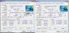
Alright, here's the deal. I've over worked my brain box and can't figure out what I'm doing wrong when it comes to making a PLL definition file. So, here are pic of setFSB with diag tab.
BCLK equivalent = 226
![[IMG]](images/storyImages/oc245.jpg)
BCLK = 219
![[IMG]](images/storyImages/oc236.jpg)
BCLK = 210
![[IMG]](images/storyImages/oc227.jpg)
BCLK=202
![[IMG]](images/storyImages/oc219.jpg)
BCLK=193
![[IMG]](images/storyImages/oc209.jpg)
BCLK=185
![[IMG]](images/storyImages/oc1.jpg)
Need a definition file for this and each of these FSB Mhz because I have to ramp up from 200mhz - 245mhz otherwise it crashes with BSOD or black screen. But I suppose since I have DUAL IDA enabled, when I run cpu.bat in the setpll directory, each FSB level in SetFSB reports as 185,193,202,210,219,226.
My goal is to run setpll like this:
setpll ics9lpr501sglf 185.193.202.210.219.226 10
Help a mod out, yo.
-
I think this would do the job:
Code:::::::::::::::::::::::::::::::::::::::::::::::::::::::::::::::::::: :::::::::::::::::::::: PLL: ICS9LPR501PGLF :: SYSTEM: HDX 9000, [email protected] (266Mhz BCLK) :: BCLKS: 185-226Mhz :: AUTHOR: 2.0 ::::::::::::::::::::::::::::::::::::::::::::::::::::::::::::::::::: :::::::::::::::::::: :: Initialisation strings :: :: [setBCLK diagnosis window OR r-w "Clock Generator" appearance ] :: 00 01 02 03 04 05 06 07 08 09 0A 0B 0C 0D 0E 0F :: 10 11 12 13 14 15 15 17 [ local3 ] :: [ local4 ] [ local5 ] :: :: Converts to be in the following format below :: :: set local0=0x0706050403020100 :: set local1=0x0f0e0d0c0b0a0908 :: set local2=0x1716151413121110 :: set local3=.................. :: set local4=.................. :: set local5=.................. :: :: The byte(s) that change during BCLK changes is substituted with :: the strings [PLL_B1], [PLL_B2], [PLL_B3], [PLL_B4] and [PLL_B5] :: from the LUT below. Ensure localx is 64-bit (16 chars), :: pad with 00 if needed. :: :: bytecount = number of bytes to be send to the PLL ::::::::::::::::::::::::::::::::::::::::::::::::::::::::::::::::::: :::::::::::::::::::: set bytecount=0x16 set local0=0x9190F0FF77FC0545 set local1=0xF2D1051C007D2710 set local2=0x[PLL_B2][PLL_B1]0323F2F4A823 goto exit ::::::::::::::::::::::::::::::::::::::::::::::::::::::::::::::::::: :::::::::::::::::::::: This is a look up table only.. this code is never run as part of the batch file :: LUT for ICS9LPRS397 PLL based on placing the two PLL byte that change in setBCLK :: when move the slider noting the BCLK they correspond to :: ::[BCLK], [PLL_B1] (byte 22), [PLL_B2] (byte 23) triple entries. 185, 08, 40 193, B6, C4 202, B6, D8 210, B6, EB 219, B6, FF 226, 76, 11 ::::::::::::::::::::::::::::::::::::::::::::::::::::::::::::::::::: :::::::::::::::::::::: Ensure the exit below is the last line :exit
But I'm not sure about the 185mhz entry, did you press setfsb for that one or not? It's best to press setfsb anyway even when you're not changing the frequency because setfsb still changes a few registers. -
Excellent! Thank you!
Yes, you are right. The one at 185 is off because I didn't hit set FSB.
Here's the corrected one:
![[IMG]](images/storyImages/oc1-1.jpg)
And seeing your work, I can see that 185 it should be B6 B0.
Thanks again for the file. I'm going to give it a shot in a while to see how it works. -
Fixed with this:
Code:::::::::::::::::::::::::::::::::::::::::::::::::::::::::::::::::::: :::::::::::::::::::::: PLL: ICS9LPR501PGLF :: SYSTEM: HDX 9000, T9300 2.5 - 3.3o/c :: BCLKS: 185-226Mhz :: AUTHOR: 2.0, Moral Hazard @ NBR. ::::::::::::::::::::::::::::::::::::::::::::::::::::::::::::::::::: :::::::::::::::::::: :: Initialisation strings :: :: [setBCLK diagnosis window OR r-w "Clock Generator" appearance ] :: 00 01 02 03 04 05 06 07 08 09 0A 0B 0C 0D 0E 0F :: 10 11 12 13 14 15 15 17 [ local3 ] :: [ local4 ] [ local5 ] :: :: Converts to be in the following format below :: :: set local0=0x0706050403020100 :: set local1=0x0f0e0d0c0b0a0908 :: set local2=0x1716151413121110 :: set local3=.................. :: set local4=.................. :: set local5=.................. :: :: The byte(s) that change during BCLK changes is substituted with :: the strings [PLL_B1], [PLL_B2], [PLL_B3], [PLL_B4] and [PLL_B5] :: from the LUT below. Ensure localx is 64-bit (16 chars), :: pad with 00 if needed. :: :: bytecount = number of bytes to be send to the PLL ::::::::::::::::::::::::::::::::::::::::::::::::::::::::::::::::::: :::::::::::::::::::: set bytecount=0x16 set local0=0x9190F0FF77FC0545 set local1=0xF2D1051C007D2710 set local2=0x[PLL_B2][PLL_B1]0323F2F4A823 goto exit ::::::::::::::::::::::::::::::::::::::::::::::::::::::::::::::::::: :::::::::::::::::::::: This is a look up table only.. this code is never run as part of the batch file :: LUT for ICS9LPR501 PLL based on placing the two PLL byte that change in setBCLK :: when move the slider noting the BCLK they correspond to :: ::[BCLK], [PLL_B1] (byte 22), [PLL_B2] (byte 23) triple entries. 185, B6, B0 193, B6, C4 202, B6, D8 210, B6, EB 219, B6, FF 226, 76, 11 ::::::::::::::::::::::::::::::::::::::::::::::::::::::::::::::::::: :::::::::::::::::::::: Ensure the exit below is the last line :exit
-
Strangely enough, it returns can't set BCLK. Wonder what the issue might be.
-
Did you try the -preview option?
If you did, what did your preview file contain?
EDIT: Also try changing set bytecount=0x18 (instead of set 0x16) in your definition file. -
Preview file contained the following for 193
When I go into rw everything and manually change the two bytes at 22 and 23, then hit write 28 bytes, it works.Code:::::::::::::::::::::::::::::::::::::::::::::::::::::::::::::::::: :: ics9lpr501sglf r-w everything file for 193Mhz :: Only commands starting with ">" are applied by r-w everything :: :: Can manually run this script with "rw\Rw /Command=ics9lprs397.rw" :: add /Logfile=Log.txt if want to see what rw does in detail :: :: Data below will be reversed of what setBCLK/rw PLL generator says: :: :: Eg: setBCLK diagnosis window OR r-w "Clock Generator" appearance :: 00 01 02 03 04 05 06 07 08 09 0A 0B 0C 0D 0E 0F :: 10 11 12 13 14 15 15 17 [ local3 ] :: [ local4 ] [ local5 ] :: :: Converts to be in the following format below :: :: local0=0x0706050403020100 :: local1=0x0f0e0d0c0b0a0908 :: local2=0x1716151413121110 :: local3=.................. :: local4=.................. :: local5=.................. :: :: NOTE: it is possible to read the PLL, perform bitwise changes :: then write to the PLL but I found it freezes my system. Instead :: I do a single hardcoded write which is very fast and reliable. :: :: If this freezes your box, then confirm that rw can read your PLL :: by running 'rw\rw', command, 'smbus read block 0xd2 0 0x16' ::::::::::::::::::::::::::::::::::::::::::::::::::::::::::::::::: :: ics9lpr501sglf r-w everything file for 193Mhz >local0=0x9190F0FF77FC0545 >local1=0xF2D1051C007D2710 >local2=0xC4B60323F2F4A823 >smbus write block 0xd2 0 0x16 >rwexit
So I'm at a loss. Perhaps it is not loading rw everything with the bat file. -
Do you get an error similar to this:
If you do, then I think there is a fix comming really soon (probably new setpll today). I will update the thread when it happens.Code:C:\Users\s\Documents\setpll10b2\setpll>setpll turbo 340 setpll: request=340Mhz, PLL=turbo. setpll: sending#1 LUT@340Mhz (09) (19) (20) (1B) (1F) to the PLL via r-w everyth ing. setpll: sending#2 LUT@340Mhz (09) (19) (20) (1B) (1F) to the PLL via r-w everyth ing. setpll: sending#3 LUT@340Mhz (09) (19) (20) (1B) (1F) to the PLL via r-w everyth ing. setpll: sending#4 LUT@340Mhz (09) (19) (20) (1B) (1F) to the PLL via r-w everyth ing. setpll: sending#5 LUT@340Mhz (09) (19) (20) (1B) (1F) to the PLL via r-w everyth ing. Failed to set BCLK
-
Yep, that's what it looks like.
-
Looks like the 9LPR S501 is unique enough that the 9LPR501 entry in SetFSB just won't cut it.
Had a hard crash that corrupted the BIOS occur. I was able to recover by removing the RTC battery to reset the BIOS then restoring defaults in BIOS.
Crash occurred when setting o/c back after resume from standby. Even so, I would get crashes when setting FSB back to 200mhz from 250mhz. Or vice versa. Or sometimes when scaling through the o/c from 200 to 250mhz.
I don't know if it is worth the effort to have SetFSB develop a specific entry for the 9LPRS501PGLF. Looking at the datasheets of the two, I can't see a material difference. It might be the HDX just doesn't like FSB overclocking - however it is wired. A hard crash like the one mentioned requires a near complete disassembly of the HDX since there is no external access to the RTC battery. Entire system board has to come up. That's a 2-3 hour job with this computer thanks to all the screws and connectors. Most other notebooks can access the RTC battery via a panel. And even if they couldn't, their disassembly would only take about 30 mins at most.
I've tried FSLx o/c which was a bust. This thing hates 266mhz FSB. BSOD before reaching the desktop, everytime. And that was at 12.5x @ 266mhz (T9300). What is interesting is that I was able to achieve ~3.325 Ghz using SetFSB (TME unlock) and Dual IDA enabled @ 13.5x, 247Mhz FSB with 1.2125v. It was stable enough to complete Intel Burn test with 5 runs at standard. With Dual IDA off (12.5x) anything over 255 FSB would freeze immediately upon being set. -
There is an ICS9LPRS501SGLF entry in setfsb, might help?
One thing you might want to try is leaving the RTC battery unplugged while testing. So that you wont have to take the notebook apart too many times.
When you did the FSLx OC, where you sure your ram was stable and you had enough CPU voltage? -
setPLL updated to version 1.0c:
http://forum.notebookreview.com/har...clocking-methods-examples-84.html#post7153216
revision.txt -
In the shareware version? I was working with the freeware version, 22.134.98. That one has ICS9LPR501SGLF and HGLF (without "s" after the "r"). Those were the two I was using to test with but settled on the former.
That's a good idea. I might do that next time. Though, when I do go back in to solder back the resistor, since it is on the topside of the mobo, it only takes about 30-40 mins to do. Where as, getting to the RTC battery adds another hour and a half. Really wish they had a hatch on this thing.
RAM was good. Used 800Mhz RAM at CAS 6. as for CPU voltage, I was able to do 3.44Ghz on 1.2125v @ 255mhz FSB with Dual IDA 13.5x using TME unlocked method. Mostly stable at that speed and voltage. When I did FSLx, it would have been 12.5 x 266mhz FSB for 3.325Ghz on 1.2v. It should have at least made it to the desktop and maybe a freeze or something. But nope, just BSOD just before reaching the desktop every time. -
I confused ICS9LPR501 with ICS9LPRS501.
-
I tried it again early today. Had some unexpected spare time so I figured why not. Dropped in a 33 ohm resistor and made sure TME was unlocked. The new Setpll 10c crashes the system with a grey screen that requires Batt and AC out to recover. This occurs at any of the 5 o/c setting levels in the definition file. Though the cpu.bat reports the proper FSB reading before o/c as 200mhz.
On my system (HDX 9000), I lose remote functionality with TME unlocked. Weirdest thing.
To test each o/c level, I did it via command line. Typed in setpll ics9lprs501pglf 226 (for the highest level defined in the def file). Did this for each level. Grey screen for all with an audio pop.
I'm going to call o/c'ing the HDX a bust. Neither TME unlock or FSLx work. TME unlock came closest but isn't reliable enough for deployment.
Thanks for all the effort though. Perhaps someone in the HDX owner's lounge might pick up where I left off. So I better document my work a bit better.
-
The setpll definition file you are using has just taken the diagnosis output from the setfsb screen. A PLL can be programmed with many variables (SRC=PLL1/PLL3, SATA clock=PLL1 or PLL3) used to define it's operation. Before calling it a bust it would require someone with a HDX9000 to open up setfsb AND then manually program the PLL in the diagnosis screen, checking for stability. It may help paying the setfsb author, Abo, US$10 to help move that process along since he's an expert at PLL programming.
Once the most compatible PLL settings are found they should be copied into the PLL definition file made specific for the HDX9000. It may very well mean then the HDX9000 can have a stable overclock. It's unusual to have such little tolerance to overclocking.
As to losing the remote functionality, it may well be sampling the signal on the same line which you have now pulled low. The solution would be to pull the signal high on the *other side* of the tme-resistor, so all lines attached there would still see a logic 1. -
Agreed. The PLL appears unique enough to warrant Abo's help. Though the data sheets between the 9LPR501 AND 9LPR S501 don't show a material difference, there apparently is.
Agreed, again.
The other issue is the loss of IR remote operation after TME unlock. This is even before o/c'ing. IR works in so far as to be able to boot the machine up (via remote's power button). But once in Windows, the function of the IR remote ceases in all aspects. That's a bad thing for a multimedia notebook that might be a deal-breaker or at least a serious compromise. Could I live without it? Yes. There are alternatives to its function, like the keyboard's multimedia functions that still work after TME unlock.
That would be difficult because there is no other side to pull up voltage-wise. After the pad, the line terminates into the middle of the board somewhere. Moreover, the line leading from pin 4, while it could be cut and then scraped to expose copper to jump 3.3v to, is really small. -
A couple of options:
1. There is a resistor further along past the pad. If that resistor runs in series with the rest of the circuitry running off the PLL pin 4, then you could put a pull up on the other side to hold it at it's original logic 1. If it's in parallel, then there's no point. Having no HDX9000 schematic available means can only do trial-and-error.
2. isolate pin4 altogether by either cutting the track leading to it (not recommended on a multilayer board). You'd be hoping that a detach tme pin would be equivalent to a logic level 0 (tme-unlock), as otherwise you'd still need to solder a resistor to GND to properly set logic 0. ICS9lprs387 m11xR1 users found detaching the TME-pin PLL leg was sufficient to disable TME - no resistor to GND was necessary.
3. lifting pin4 and if necessary attach your pull down resistor directly to it. This is challenging given how small the PLL leg is. If you did want to detach the tme pin 4 I'd suggest ask a mobile phone technicial with the fine soldering gear to do it so you can always re-attach it. If it works without needing a pull down resistor, then great - you've opened the door to other HDX9000 owners to very simply detach/lift that pin using basic equipment such as a sharp needle head.
Solutions (2) and (3) would keep the circuitry running off the tme pin was at it's pre-modded logic level, so your multimedia functions would work. This may also increase overclock stability as I've found HP schematics often have other SMBUS sensors/signals linked off the TME-pin.
@Moral Hazard - did you try to tme-unlock your Toshiba A9 by just disconnecting the tme pin? -
Excellent suggestions. I think I might try cutting the track. That worked when I was doing the FSLx mod. I can always solder it back. I have semi-fine gear so I might even try cutting the leg of pin 4.
Thanks again Nando. -
I did try removing the resistor that was connected to the TME pin (effectively disconnecting the tme pin). System wouldn't post in that config.
-
New plan of attack:
Thinking back to when I was a kid making logic gates with diodes, I came up with an alternate approach.
Here's a diagram I drew of it...
![[IMG]](images/storyImages/flowchart.jpg)
Only issue is that the diode drops 1v. Pin 4 of the PLL apparently feeds voltage to the IR section of the HDX 9000. Using a diode would allow it to continue to feed most of that voltage (2.3v) but would block the majority of signal voltage going to pin 4 at start up so TME = 0. -
SetPLL was updated to version 1.0d.
Revision.txt:
Code:1.0d (3-1-11) Commandline syntax changed. If using -preview it must be first. Added PCIE clock options to commandline. Using new r-w BSWAP command (swap little/big endian) so can now create LUT.bat files by transcribing setfsb format directly. Changed existing LUT files to setfsb format. Added PCIE clocks to ics9lprs387/397 LUT files. Updated r-w everythng to 1.4.9.1. -
Won't work D:
Well I didn't try too hard on this software, but I tried setfsb, and it didn't work.
I can read ICS9LPRS365BGLF fine, but I can't set the fsb speeds.
Also on throttlestop, I couldn't get it to overclock my laptop, only underclock.
I have a vostro 1310 with a t8100.
Help? -
Can you please upload a screenshot of the setfsb diag tab (after selecting PLL and pressing getfsb, click on diagnosis)?
-
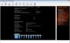
I have ICS 9LP306BGLF which cooperate which intel 945gm.
![[IMG]](images/storyImages/mbpll.th.jpg)
ICS9LP306
I dont know is it locked or no, I couldn't find datasheet of it but only
use case in model of my lap.
![[IMG]](images/storyImages/pllics9pl306.th.png)
ICS9LP306 pinout
Yet another problem that I have is SetFSB doesn't recognize this PLL
![[IMG]](images/storyImages/setfsb.th.png)
ICS9LP306 SetFSB
And I stuck with no idea do I have any chance to bump FSB up or no
-
Absolutely,
![[IMG]](images/storyImages/13327165.jpg)
-
You don't have TME mode enabled, so you should be able to overclock.
You can try something like this:
http://forum.notebookreview.com/6188065-post115.html
If TME is bit 6 of byte 9 then it's enabled, but without the datasheet we can't be sure.
One way to overclock would be to connect FSLA to GND (get a 200mhz FSB). But that might not be possible because that pin is also used for the USB clock. I'm not sure if you will be able to overclock or not. -
Are you sure?
![[IMG]](images/storyImages/13823212.png)
It looks like I can't, I think
I have for 09h(90) I have 01000100 (44)
If the only way to get past this is to solder in a resistor, I'm not too sure it's a great idea.
Any other mods like taping a pin or something and it gets a higher FSB? -
In the screenshot you've posted the value of byte 9 is 25. So that's 0 0100101. Seems like TME is disabled to me.
-
Hi all
This is my first post in this forum and wanted to show you my
situation asking for your help. I've read the 89 pages of this forum and first of all wanted to thank Moral Hazard, Nando (vidock experiences too) and all other members by the effort in trying to help all the users. i had an experience modding a celeron with changing their voltage (BSEL) and increasing there FSB, but this one looks more difficult because their complexity and because the size of the ICS chip.
Sorry for my bad English
My Hardware
Toshiba A300-188; Santa Rosa Platform; PM965; ICH8-ME; dual core T8300 2.4GHz; Peryon; socket P(478); 2 X 2GB Samsung M4 70T5663QZ3-CE6 5-5-5-15; ICS 9LPRS365BGLF ; Mobility HD 3470 680/500 @ 790/594(Riva Turner)
CPU-Z
See an error on multiplier CPU-Z most of the time show X13 instead of X12, but my processor is a T8300 2,4GHz not 2,6GHz.
SetFSB
View attachment m199.9MHz [].bmp
Reg 09 is 65, if i change bit 2 to 0 (apply) the computer doesn't freeze.
ICS 9LPRS365BGLF
-Pin 4 i think is connected to R2 , but exist point 1 that i don't know if it is connected to the other side of the board, seems a little bit difficult to apply the TME-Unlock!!?
-Pin 57 hard mod, 200=>266 does memory change from 667=>880, i think is too much for my memory!!?
-BSEL i think is not applicable on this case dual core T8300
-My mobile Hd 3470 is overclocked, does the change of the FSB affects the Frequency of the pci-E? must i first disable the overclock
Thaiphoon Burner
Can you help me to try overclock -
13x is because of intel IDA I think.
You can try this, will get you 13x all the time on both cores:
http://forum.notebookreview.com/win...c-acceleration-ida-both-cores-core-2-duo.html
Yes, looks difficult, not sure what would happen if you ignore point 1.
You might get lucky
Must flash the SPD with 800mhz timings (or higher) for the 667mhz frequency.
That's true.
PCIe clock should not be linked to the FSB, so this would not be a problem. -
I Thanks for the reply,
We see that the only solution is FLSx method and flash memory speed.
What is the best software to flash the memory, may i only change the cas latency to 6 or must do more changes?
My memory timing tamble (Samsung M4 70T5663QZ3-CE6)

Settings of 800mhz from Thaiphoon Burner (Samsung M4 70T5663QZ3-CF7)

If the option is more then the cas latency settings, the last options must be
tRRD=4; tWR=6; tWTR=3; tRTP=3 (higher values of 800mhz and 600mhz)
tRRD=3; tWR=6; tWTR=3; tRTP=3 (800mhz values)
tRRD=4; tWR=5; tWTR=3; tRTP=3 (667mhz values)
or 233mhz with 333mhz values
Can i only connect the pin 57 to 58 directly to do FSLx method work? -
I would first try with thaiphoon burner, if that doesn't do what you want, go for SPDtool.
I don't know, you will have to experiment I guess.
If the notebook can get into windows with only the cas at 6, you can use memset to play with the rest of the timings.
That might work, but I would prefer to be safe and use a resistor. -
hello everyone:smile:
i recently successfully implemented my DiY Vidock on Acer Extensa 5620z-4810 and i also flashed my motherboard BIOS to DUAL IDA and upgraded my Processor to a Core 2 Duo T7500. i successfully managed to run my T7500 from 2.20Ghz to 2.4Ghz by locking the multiplier using Throttle Stop
unfortunately, the CPU performance is still not enough and i need to find a way increase my CPU performance.
i tried using SetFSB but as soon as i change the clocks my computer would lock up
i checked the status on register 9 bit 6 using SetFSB PLL Diagnostic and i can confirm that i have a TME-Locked because the second Digit is 1
i saw that there is a possible way to overclock using the software method as demonstrated with ics9lprs355
unfortunately i am not a computer programmer and i can't decipher what individuals bits mean and what to do with them. i also don't have experience on doing a hardware mod so i would like to try every single software workaround possible to enable overclocking on my computer
one of the reason i want to overlock my computer is because if i overclock my FSB, according to the DiY Vidock post it would also increase my PCI-E clock so the Performance of my DIY Vidock will also improve in the process
i tear apart my computer to its bones and i finally found its ICS deep within its shell
its ICS is
8358124
0806
9LPRS502PGLF
i googled my ICS but i can't find any link that i can download its datasheet
i am willing to take the risks involved in order to achieve my goal. i already set my mind that i want to overclock this thing no matter what it takes even if i broke it in the process
i want to overclock my computer to 2.8Ghz or achieve a milestone with 3Ghz+:wub:
if there is absolutely no way i can use a software method overclock then so be it. i will also consider doing a hardware mod provided that the tools and materials for doing so would be reasonable
i hope you guys can help me to achieve this milestone
-
The 9LPRS502PGLF is likely very similar to a 9LPRS501PGLF for which Moral Hazard has explained in detail in Method 1: TME-unlock a PLL to allow software overclocking on the first post on how to apply the TME-unlock PLL pinmod. Summarized as:
- The G in the model means it's a TSSOP (rectangular) PLL package for which a TME-unlock is set by applying a logic 0 to the PLL pin4.
- Do that by following the track leading off pin4 to a nearby resistor. Lift the other side of the resistor leg to isolate the resistor from the rest of the circuit. Run a patch lead to GND, a nearby screwpoint, to the lifted resistor leg. Place some insulation tape below the resistor so that it never becomes part of the circuit again.
- OR run a 22-100 ohm resistor on the TME-side of the resistor leg to GND. This is a strong pull down resistor that will set the TME pin to logic 0.
Confirm TME-unlock is now set by reading the TME_Readback flag, register 9 bit 6. Then proceed to use setfsb or setpll to program the PLL. The 45nm T8100 you were deliberating over prior to purchasing your T7500 would have been a better choice for overclocking purposes since it runs cooler. But nevermind, see if you can get a decent T7500 overclock.Last edited by a moderator: May 7, 2015 - The G in the model means it's a TSSOP (rectangular) PLL package for which a TME-unlock is set by applying a logic 0 to the PLL pin4.
-
I found the pll in my netbook (toshiba nb500), it's rtm890n-397. Can't find a datasheet for it, guessing that the pinout should be similar to SLG8SP556 (I think), because one notebook uses both those plls.
Now the m11x uses both the slg8sp556 and ics9lprs387, I compared those 2 plls and they have the same pinout. That means my pll must have the same pinout as ics9lprs387.
So I think I know how to disable TME and also do an fslx mod, but I'll try it later when I have a second notebook to fall back on if anything goes wrong. -
i never thought i would go this far because i thought the T7500 @ 2.4Ghz would be able to let me play smoothly but i was wrong and now i need to find a way to increase CPU performance.
for the T8100, for sure if i only knew i would go this far and do this modding, i would have pick that instead xD
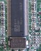
yes the ICS is indeed rectangular shape but the total pin is 56 because it is shorter
![[IMG]](images/storyImages/123123xy.jpg)
i can see that the nearest resistor closest to the Pin 4 has 2 ending points
im sorry but what do you mean by " Lift the other side of the resistor leg to isolate the resistor from the rest of the circuit"
do i need to literally "lift/remove either end of the resistor?
what do you mean by "Run a patch lead to GND"?
what is a patch lead btw?
what is GND how can identify?
i still have left over 75 ohm resistors from my previews Ultramon/Chung-Gun Internal LCD setup
6 Resistors 1/4 Watt 75 ohms metal film 1% - eBay (item 180501881515 end time Mar-27-11 15:30:40 PDT)
since it seems that hardware modding is my only option.
what is the best possible mod for me that will give the best absolute result?
i don't have any tools for this modding so i need to get it.
so what i need is a soldering iron?
do you guys know any soldering iron that is cheap?
i want to get the cheapest stuff that will do the jobLast edited by a moderator: May 7, 2015 -
i need help guys!
i tear open up my laptop again and what i did was get the left over transistor from my Ultramon/Chung-gun and put it on the resistor for the nearest pointing resistor on PIN4 and put the other end of it on the nearest screw using a tape
what happened was when i boot my computer, i hear a slow clicking sound(not from my hard drive) then slowly but gradually it becomes louder and faster(i never had that sound before @_@)
i also open SETFSB and check the status on register 9 and the #1 on the second digit is gone and when i try to overclock my bus using ICS9LPR501SGLF
it did work. i can now adjust my FSB and cpu-z is reporting the clocks i selected without crash
i am really worried that the clicking sound will have a bad effect on my computer and it sound is just super annoying and it is getting on my nerves
please help me get rid of the clicking sound asap
edit:
![[IMG]](images/storyImages/picture7jn.jpg)
-
Clicking sound, which area of the notebook does it come from?
Did you make sure the speakers were muted? -
the sound starts even before it would post
it seems like it is coming from system speaker or something -
Can you disconnect the speaker?
-
i manage to make the sound disappear
what i did was remove the tape and make sure it is not making any contact with other transistor.
i can now set the FSB to 230 but as soon as i go 235 my computer would lock up
-
it seems that it is getting loose
i need to get an soldering iron
do you guys know any cheap soldering iron that will do the job? -
To maximise your overclock possible alter your system as noted below:
1. Set your x3100 graphics' Power Settings using igfxtray to the more overclock tolerant "Maximum Battery". The key option that allows higher overclocking being "Intel Rapid Memory Power Management".
2. Increase your CPU voltage. Overvolting will give more CPU stability.
3. Change your RAM's 333Mhz SPDTable entry to have CAS=6, matching what a 400Mhz SPDTable entry would have. Do this using ThaiphoonBurner or SPDTool. Moral Hazard has an example on how to do this on the first post. This will give RAM stability since at your 235Mhz BCLK you are running RAM at 391Mhz.
PS: Consider using the Macro function of your camera to get clear close up pics of the TME-unlock PLL pinmod you are doing.
For the DIY ViDock you may well find that a pci-e overclock of 10-25% will yield noticable improvements in framerates. A CPU overclock will help as well.Last edited by a moderator: May 7, 2015
PLL Pinmod Overclocking Methods and Examples
Discussion in 'Hardware Components and Aftermarket Upgrades' started by moral hazard, Jun 24, 2009.


![[IMG]](http://img98.imageshack.us/img98/217/mbpll.jpg)
![[IMG]](http://img156.imageshack.us/img156/9445/pllics9pl306.png)
![[IMG]](http://img69.imageshack.us/img69/8490/setfsb.png)

