
You should be able to overclock the 6910p with a pll mod. The SLG8SP512T goes up to 1600 MHz (400 MHz x4), so that's not a problem.
The T9300 has an 800 MHz FSB = 200 MHz x4, so the mod seems rather easy - connect FS_B to ground via a ~10k resistor. That should give you 3.3 GHz or 3.5 GHz with dual IDA. Soldering is the hardest part, though...
The problem will be with the RAM and CPU voltage, but you can flash the RAM using SPDTool and as for the CPU voltage, I'd recommend using a modded BIOS that disables EIST on boot so you can boot with the CPU at the lowest frequency, then use Throttlestop to set it to 3.3 GHz and set as low a voltage as possible.
That's what I did with my 8530p and it works great, I believe the 6910p BIOS should be just as easy to mod. I'm finishing the modding right now, I'll report back after assembling my laptop.
I don't know about TME unlock, it was really hard on my laptop, but the PLL FSB hardmod doesn't depend on it (in fact you can probably do them both)...
-
Thanks for reply.
I'd prefer do not mod Bios (actually I have the latest HP 1.7), UNLESS I am sure that the new one only solve problems and not creates others, and mainly that remains to me possibility to come back (downgrade) if something is wrong.
Then I think that only I will mod the PLL pin FS_B.
But what about the compatibility of the chipset GM965 with a FSB of 1066 Mhz?
Another thing that I not understood is:
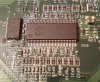
I have FS_B / TEST_MODE on Pin 57, and GROUND_REF on pin 58 (See pictures).
Probably this is an ideal condition, if I can short directly Pin 57 and 58, but I think that so is not correct.
I will must desoldering pin 57 before to connect it to Ground?
-
Yes, you'll need to cut off pin57 from the rest of the motherboard, so that makes it a bit more difficult (and hard to reverse).
You must not short the pins directly. With the T9300, that would probably damage something.
Ideally, you'd want to trace pin 57 further away from the chip (hopefully there's a long clear strip somewhere), cut its connection to the motherboard (with a box cutter, for example), then connect it to any ground point (even a screw nearby will do fine) via a ~10k resistor - this is pretty important. So the cable would go Pin57->resistor->Ground.
You could just cut the pin57 connection and leave it at that, it should work but it's possible that it would occasionally lock up (especially when waking up from sleep). You can test this with the board outside the laptop and an external monitor, if it works fine, then there's no need for the resistor.
PM965 will work at 1066 MHz, even 1333 probably, but you'll need to voltmod the CPU (OR use an edited BIOS), because the CPU would boot at 3.3GHz, and the default voltage won't be enough, so it would lock up or BSOD shortly after BIOS POST.
RAM may need to be flashed because it would work at higher frequencies - in my case 800 MHZ RAM runs at 1000 MHz, so I flashed it down to 667 MHz and now it runs at 830 MHZ. In your case, you'll go from 667 MHz to 533 MHz, and also lower the timings to speed it up. But a lot of 1-2GB 667MHz modules will run fine without any mods.
By the way, DON'T flash the latest HP BIOS (F19), as I think it's irreversible and you can't mod it - leave it at F17! -
Thanks a lot for your detailed explaination.
If I cut Pin 57 and I connect it to ground via a 10K resistor, the TEST_MODE function of the pin may be it will be lost (as I think). Or not?
About the BIOS update It's too late!!!!!!!!!!!
When I read your reply I remembered that already updated my BIOS to Ver. 68MCU F.19 3 months ago!!!
When I written my post I was convinced that the latest Ver. of HP BIOS was Ver F17, but in reality I have Ver. F19.
It's a pity!
I hope that this is not really irreversible, and hope that someone have tried to mod this Bios version.
If I know correctly the "bad" BIOS version of your Lap is F.20. released in Dec 2011.
Mine is been released in June 2010. May be that in that date HP not introduced yet the trap in the BIOS? -
It could be that the BIOS is not encrypted, which would be a good thing.
TEST_MODE is useless for the user (it's activated when it detects a certain voltage, most likely 3.3V, and I'm not sure what it's used for, but it's not used in normal operation). For FSB settings, you either connect to ground (for a "0" on the table) or sub-1.5V (for a "1").
If you're gonna try the mod, you'll need a multimeter and a small soldering iron or a DIY soldering tip.
I could look for a good cut/soldering point if you can upload a few photos of the board around the PLL chip. Safest way would be to cut the trace somewhere where it would be easy to solder (and reconnect it if it doesn't work - with solder or just a pencil).
But I gotta say that if you overheat the trace it can rip off the board and you can risk ruining it - if you're not experienced this mod is quite difficult (I found it rather easy but I've got some experience with this stuff and a good small soldering iron)... -
Hi,
This mod can be made with a resonable safety and % of success only by peoples with a good experience in soldering.
Fortunately I have.
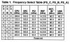
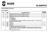
I read more carefully the datasheet of SLG8SP512P PLL, and I understood something important that probably may change/offer other point of view about the FSB pin mod.
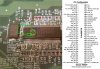
As you can see in the register table, the last 3 bits related to the FSB are "Read Only" bits.
This means (as specified in the description column) that the PLL during the Power_Up read and sample the current state (Low/High) of the 3
FSB_A/B/C pins, and store the 3 values in Bits 6,7,8 of his internal Register_0.
After, FSB_A/B/C pins will can also ideally disconnected without problems and the set CPU clock will continue to be generated.
In other words differentely from other PLL, in this chip the register_0 cannot be write by an external software ( i.e SetFSB) and probably for
this reason SetFSB do not include the SLG8SP512P PLL in the list.
Probably, this open other and new mod possibilities, for example to add a very simple electronic circuit (with very few components) able to
generate a single brief Low-level pulse (i.e. 1 Sec.) to connect directly to Pin 57 (in my case), without any need to cut pcb traces or mod original circuit.
For now this is only an idea and I will to study better this possibility, and also hope that someone more expert than me can give an help to evaluate and/or develop it.
-
That's out of my area of expertise, but I think it would not be possible to set FS_B to "0" without cutting the pin's connection on the motherboard in this case since the CPU is setting it to "1".
As I understand, these pins are set to "0" by default and set to "1" if voltage is sampled, which is why in my case (with the SLG8SP553V) I could do the mod by simply connecting a 3.3V line to pin7 via a resistor.
So, since the CPU is trying to set it to "1" and your circuit would be trying to set it to "0" at the same time - it would just be set to "1", error out or worst case, be damaged - how can the chip choose what to write to the register? -
You are right, probably there is no way to avoid to cut pin and/or some track on PCB.
I will must to inspect accurately the PCB around the PLL, with the hope to see some shorted bridge on the track that can avoid to cut it.
I also will take some detailed photo of the PLL area and I will post it. -
Thanks for the detailed reply. Just one quick question. Did you need to cut the FS_C pin before connecting it to the 3.3V?
Thanks -
You don't need to cut it IF the processor is a 1066 FSB unit... It's possible even to wire the resistor through a switch or jumper so you can disable it without disassembling the laptop if need be...
-
I have a SL9400, so yes it's 1066Mhz according to Intel here. What kind of switch would I use?
Thanks -
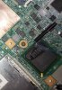
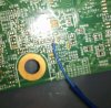
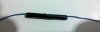
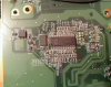
So I finished my mod a while ago, but courtesy of Android I lost most of my photos (instead of uploading it to Drive as I intended, it just fu**ing deleted them without confirmation).
Anyway, I've recovered a few of them - you can see the resistor "package" (two resistors in series wrapped inside the electrical tape). The 3.3V source was taken from the pads I highlighted in red, and I found a more suitable soldering point for the pll pin on the other side of the board.
Everything works fine, except my T9900 can't do more than 3.5GHz (well it can, but is unstable in Prime95) AND it's limited to 1.1875V maximum voltage - kind of a disappointment since I was going for 4GHz") .
.
The North Bridge also heats up a lot - the mod added ~7 degrees to it compared to the default 266 MHz FSB, it easily climbs to 95 degrees under full GPU+CPU load (everything's on the same heatpipe). If not for my heatsink mod, it would overheat for sure.
I'd say the PLL mod is worth it for anyone who wants to get more out of their aging laptop - most Core 2 Duos should do ~500+ MHz over their rated frequency relatively easily. You'll need some soldering skills and a small soldering tip (can DIY out of copper wire).
Boot up clocks problem solved by modding BIOS to boot at lowest multiplier (basically disable EIST, then use Throttlestop in Windows).
RAM flashed to 667 MHz (= works at 830 MHz with PLL mod), 5-5-5-15 timings using SPDTool (better than Thaiphoon for DDR2 memory!). By the way, if you get a no SMBus detected error, run HWInfo, it makes the SMBus visible for all programs!
 capitankasar likes this.
 -
i have hp dv6-3063 with config corei7-720qm 8 gb ram ddr 3 and amd 5650.i found my clock gen. model from motherboard's schematic and it is 9LRS3197.i have searched in google and found someone do change BLCK from 133 mhz to 176 mhz.How i can do to this? please help
-
Greetings to all. It's my first post here.
I have a question about SLG8SP512T, but from another laptop, AMILO Si2636, (Santa Rosa, AFAIK), GM965 chipset.
Native CPU was T8100 and successfully upgraded with T9300.
Reading this tread I found the same PLL, and now thinking about PLL FSLx mod.
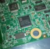
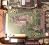
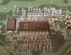
Here few photos, is it correct circuit with resistor to 58 pin?
Or connect 57 pin with resistor on main ground?
-
Can you please advise me about SLG8SP512T?
I have doubt.
Connect pin57 through resistor on pin58, or (as I read somewhere) connect pin57 through resistor on main ground?
Which way is correct? -
Connect pin 57, which is FSB to the ground with resistor after disconnecting this pin eg.by cutting the trace. Your goal is force FSB low making it read as a "0" since now it's high = 1.
-
Good Work!!
-
Hello,
I have a HP 6730b Notebook, and when I will set the BCLK the tool failed with the following reason: Failed to set BCLK
Can someone help me?
Regards -
Hi there! It's been a while since I've posted on this forum, so I'm a little out of the loop.
A year or so ago I discovered the PLL for my laptop (Studio XPS 1640). The model number is SL28541. Unfortunately RW is unable to read the contents and the SetFSB SL28541BQC profile only give me the reading "byte error". It's odd given that some of the ICS profiles don't give error messages. Is it possible that the pins used for communication aren't accessible or something?
The information surrounding the subject is patchy at best, but the underlying principles seem simple enough. If anyone could give me a quick briefing on how things interface and fit together then that would be much appreciated. -
Hello guys,
I have a big problem and hope for your help. I have a Clevo M980NU notebook equipped with a Intel T9500 CPU and cannot manage to apply the BSEL and VID Mod..
I´ve tried to apply the Mod but it seems not to work at all. The FSB doesn´t change and remains locked at 800Mhz.
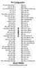
Having found a a service manual of my notebook, I´m pretty sure it is suitable of handling a 1066Mhz FSB. ( just google "clevo m980nu service manual" )
Here are some details you may need to know in order to help me out ? I´m not sure if it´s ok to hotlink the complete service manual.
![[IMG]](images/storyImages/mainboard-specsenx1u.png)
![[IMG]](images/storyImages/system-block-diagramcwa9g.png)
I´ve connected BSEL1 to VSS in order to obtain a 266Mhz FSB but nothing happens?
Would it be a good idea to try to enforce this kind of connection ?
![[IMG]](images/storyImages/t9500-bsel-266mhz-for30ar9.png)
I´m willing to risk a hardware mod too, just in case I need it in order to convince the Bios to accept the BSEL Mod..
Best regards and thank you for your time, -
is that a good enough image to tell?
RTM875T-606 datasheet & application note - Datasheet Archive
http://forum.notebookreview.com/har...clocking-methods-examples-23.html#post5457881
is there enough information here to tell if it's locked? if it is locked is there enough info to figure which pin needs to jumped to ground?
Toshiba L305-S5917
EDIT: http://forum.notebookreview.com/har.../429717-rtm875t-606-info-gathering-ocing.html -
i overclock a dell d630 by removing its leg and without speedstep cpu lock the multiplier to 6x and when i solder the pin 45 to ground cpu fsb return to 200 and disable the overclock there is any way to keep multiplier in it's full 12x
-
Hi, can someone help me to overclock my Lenovo T61 (Widescreen)
Here is the overclocking method im trying to follow (page 121) : http://forum.notebookreview.com/har...pinmod-overclocking-methods-examples-121.html
This is what have done at the back side of the pcb:
![[IMG]](images/storyImages/dfy8mx.jpg)
The layout of the front side of the PCB is a little bit different than the layout in the pictures in the guide, i suspect this is because he had 4:3 screen and i have a wide screen. What should i connect?
![[IMG]](images/storyImages/2nm1y8k.jpg)
-
do they use different boards?
-
the square and widescreen models use a slightly different layout. one person here have said that they confirmed to overclock with the widescreen model.
-
Anyone help?
-
anyone can help me i put different resistor between pin45 and ground i try 10k 5.6k and 100 ohm resistor and try to overvolt by vid mod but multiplier stuck at 6x does if i change its t7500 cpu with an amd cpu multiplier will back to normal state
-
Hi
I have overclocked my Lenovo T61 laptop, by changing the fsb from 200 to 266. My Lenovo uses the intel GMA965 (X3100) Onboard graphics, so increasing the FSB has also overclocked it. Now I have run into a problem, where if I install the graphic drivers, I will get black screen as soon as I boot into windows. Can I fix this?
Can I can overvolt the onboard graphics?
Can I underclock the onboard graphics? -
It might be a better idea to use a POT, so can you change the resistance at any time if you need to.
-
what is a pot,i thing if i use a bsel mod to underclock cpu it would work does there is a mod to downclock a socket p or overvolt cpu when eist is stoped
-
Potentiometer.
See:
Potentiometer - Wikipedia, the free encyclopedia -
at last i wire mod vdi4 to vss and cpu get unlock at full multiplier with speedstep enable at 3200mhz
CPU-Z Validator 4.0
 cdoublejj likes this.
 -
i bsel mod this cpu for 333mhz bus speed but computer dont turn on with mod i think this is for memory limit does i can change memory timing and dram frequency for bsel mod to 333mhz by cpu or pll moding
-
Did you try 333Mhz with a 6x multiplier? 333Mhz fsb with the stock normal multiplier is too high for that CPU. You also might need to slightly overvolt the northbridge.
-
Hi,
Another overclocked laptop, the Dell Precision M6400.
I just put a little wire one the socket to put BSEL2 to VCC. Fsb Goes from 266 to 333 Mhz and the P8700 goes from 2,53Ghz to 3,3Ghz.
It is a jump of 20% in performance.
The INTEL Chipset does not see the BSEL MOD and don't lock the processor multiplier to 6x....I'm Lucky.
Will try next week end with my other M6400 with QX9300. If it works, It could be a 3,3Ghz QX9300 laptop, quite good.User32, alexhawker and capitankasar like this. -
The QX9300 already has an unlocked multiplier. There is no reason to try to overclock it via the FSB. You can determine the optimal multiplier and voltage using throttlestop. Then you can pin mod the multiplier and voltage to get it to work just how you want it to.
-
Yes I know but what a overall performance jump when you boost the FSB!
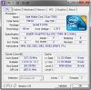
Here is the proof with the QX9300 @4Ghz:
CPU-Z Validator 4.0 -
Good work on your overclock.
PLL Pinmod Overclocking Methods and Examples
Discussion in 'Hardware Components and Aftermarket Upgrades' started by moral hazard, Jun 24, 2009.


![[IMG]](http://abload.de/image.php?img=mainboard-specsenx1u.png)
![[IMG]](http://abload.de/image.php?img=system-block-diagramcwa9g.png)
![[IMG]](http://abload.de/image.php?img=t9500-bsel-266mhz-for30ar9.png)


![[IMG]](images/storyImages/bebprb.jpg)


