
hey guys, and moral hazard,
i had msged u in email and u told me to check out this post. so here i am.
here is my laptop info:
Dell Inspiron 1525 Laptop with T7250 CPU (2ghz, 800mhz) ram @ 667
MODEL: 0U990C
CHIPSET: INTEL GM965 REV. C0
SOUTHBRIDGE: INTEL 82801HBM (ICH8-ME)
LPCIO: NS
BIOS: A13 (LATEST - 6-27-08)
PLL: ICS 9LPRS365BKL
---
i would like to go ahead and try this pll mod. any thoughts on the matter would be appreciated.
thanx!
-
hi FieroGT, welcome to NBR

Can you download setfsb from here:
http://www13.plala.or.jp/setfsb/
In setfsb select:
ICS9LPRS365BGLF
Then click on the "diagnosis" tab.
then click "getfsb".
Please post a screenshot of setfsb when you have done that.
Also can you try moving the top slider a bit and press "setfsb" and tell me what happens?
FYI, here is the datasheet for your PLL:
http://www.darksmileysystems.com/downloads/criterion/e-wrecked//9LPRS365-SPEC.pdf -
Well, i think you should hold litle bit and use SetFSB at start to see if you can oc your laptop with pll selected as ICS 9LPRS365BGLF since these plls are quite similar, if that would work then you would not need hard mod your pll.
-
OK, 1st i would like to say that i have previously DLed and tried setfsb with my laptop and it wouldn't work. i then emailed abo and asked him to add my pll, and gave him all my info. he then looked into it and replied to me with the bad news that my pll is 'locked', and cant be modded with any software. I'm guessing this locked mode that he talked about is the same thing u mention as TME enabled?..
ok, now to the work at hand... i went and ran the latest setfsb again as u suggested, and selected ICS9LPRS365BGLF as per above suggestion and it's very close to the pll i have. the good news is that it did come up with all the correct current bus speeds and stuff, so it seems to be reading the pll ok?. bad news is though, like abo said, any changes i attempted to make and apply simply did nothing at all.
Here is the screen cap:
![[IMG]](images/storyImages/setfsb-cap1.bmp)
I look forward to your replies! -
@FieroGt
Your PLL is locked through TME. Offset 09h must be 25 instead of 65 to be able to overclock. -
ok, thats what i thought.. so this means i am a candidate for the pll mod then?
and if so, would that mean that after i unlock my pll with the mod, that setfsb should work with my pll using that one that was real close? (ICS9LPRS365BGLF) -
Edit:
Forget this post, I'm still half asleep
-
yes, and FYI when abo says locked he means TME is enabled.
yes.
Now can you please take a photo of your PLL so we can see if there is a resistor connected to the TME pin.
Your PLL is either like myne (where the TME pin is pin 4).
Or if it is the other shape (square), then your TME pin is pin 11.
just look at the datasheet I gave a link to, it shows everything. -
sweet! I'm loving the quick replies!
i went and looked at the datasheet, and it says my TME is pin 4. (PCI2/TME)
so , what i gotta do next is tear this lappy apart once and take sum pix 4 ya, and go from there.
i'll get into that 2morrow, as its 3:17 am here now. -
ok, I'm on this forum every day so take your time
-
well mortal, whats your oppinion? since pinmod the cpu socket didnt work (266fsb) should i go for the modifying pll mod for 266fsb?
If i should, what pins i should now mod to get 266fsb? -
hy guys, especially you, moral hazard ...
I hope I can give some ideas on increasing the FSB to the next laptop
laptop info:
ACER Extensa 5220 with T7100 CPU (1,8ghz, 800mhz,2Mb L2) ram 2x 1GB 667 DDR2
CHIPSET: INTEL GL960
SOUTHBRIDGE: INTEL 82801HBM (ICH8-ME)
BIOS: ver 1.35 (last)
PLL: RTM875T-605
![[IMG]](images/storyImages/rtm875t605frf.jpg)
Like as FieroGT, I would like to go ahead and try this pll mod.
Thanx!
P.S. sorry for my english... -
I would also like to try the PLL mod if possible in my laptop.
HP DV9700
C2D T5750 667FSB 2.0Ghz
4Gb DDR2 667
Intel PM965 Chipset w/ Nvidia 8600m GS
PLL- RTM875T-606 -
I don't know why it didn't work.
If you could take a photo of the PLL then we can see how easy it would be to mod it.
If there is a resistor on FSLb then it would be easy so maybe you should.
But if it's not easy then probably not worth it
your datasheet is the same as the one in this post:
http://forum.notebookreview.com/showpost.php?p=5332281&postcount=102
You would have to change FSLb to 0 to get 266mhz.
Your PLL comes in two shapes so we cant guess which pin it will be until you open up the notebook.
(If you could post a pic if you do it?) -
Ok, I'm looking for the datasheets for your PLLs, if you have them please give me a link so I can take a look
EDIT:
also can you download setfsb and select RTM875T-587, then click on the diagnosis tab.
then click on "getfsb" and upload a screenshot here.
Also test RTM875T-587 to see what happens when you try to overclock.
It's important to find the datasheets, so please look for them if you have time
-
ok, i tore my laptop apart just now and found the pll, unfortunately, its not the normal rectangular shape as most are. and it doesn't seem to match the 1 in the datasheet u posted, but i dont remember for sure, cuz now the link isn't working. the pll i have is perfectly square. tryin to find my cam now to snap a pic once....
-
I know the PLL, I have seen it before.
It is in the datasheet I gave if you scroll down a few pages,
your TME pin is pin 11 (if I remember correctly).
Please do upload a photo so we can start working on how to mod it. -
ok, i found my stinkin cam, but now the batts are dead
so they are charging now
about to try and snap a few pix quick!! will be right back...
also, i had saved that datasheet on the laptop yesterday, but prob now is, its all apart, so i cant get to it... and the link appears dead...
so u have another source for it maybe? -
@FieroGT and rail3r85, I can't attach your datasheet to this post because it's too big.
If you want it and the link I gave doesn't work then go here:
http://www.datasheet4u.com/download.php?id=650606
*You have to scroll down and click on "datasheet view".*
The datasheet contains two pinouts, one for the rectangle and one for the square shaped PLL. -
![[IMG]](images/storyImages/ics9lprs365tme.png)
Need to connected TME/PCI2 pin 11 to GND via a 10k resistor to disable TME mode and allow software overclocking. -
yup! that looks like it! i will still take a pic here and send u once to make sure b4 i start to soldiering!
-
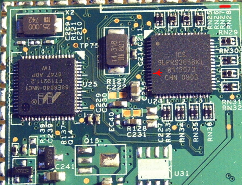
ok heres the pic:
i used red line to show the pin i think needs the mod..
it seems to go over a tiny bit to the left, then into a hole.
![[IMG]](images/storyImages/1a.jpg)
-
I cant see the pic?
-
hmm i can see it here? lemme try sumthin else
ok its attachment here
also, i was readin yer 1st post, where u said if the system still uses the PCI2 sig after boot then it wont work.
do u think this may be a problem here? or is there no way to know until i try it?Attached Files:
-
-
Thanks, actually it was my problem, now I changed my internet from wifi to mobile broadband and I can see the pic
there is a quick way to check that actually, look at the datasheet page 19.
you can see that Byte 2 is an Output Enable Register.
you would have to change bit 2 of byte 2 to 0 to dissable PCI2 to test whether there is a problem or not.
So open setfsb, select the closest PLL in setfsb.
click on the diagnosis tab, then click getfsb.
now look at register 2, change bit 2 in register 2 to "0".
It should dissable PCI2, if you get an error or BSOD then you cant do the TME mod.
But if nothing happens then you are fine to continue with the mod. -
ok, i went and did that. and good news is the laptop still works!
but bad news is that TME is still enabled.
i dont know how far grounded that pin needs to go to disable?
because now with the 10k inline to GND, the v on pin 11 comes to 1.6v still. (and as i understand its 3.3 stock)
so maybe its not pulled enough to GND yet? maybe i need a lower resistance?
i'm not sure what else to do at this point, so i'll await your replies on the matter b4 proceeding any more. -
you need to disconnect the TME pin from VDD first I think, before you connect it to GND.
So in your case I would suggest using a DMM to do some continuety tests with the "hole" to see where it goes.
Follow the track from pin 11 untill you get to a resistor, then dissconnect the resistor.
Otherwise I think you would need to lift the TME pin from the motherboard, which is highly risky since it's unlikely you will be able to reverse the mod if something goes wrong.
Or you could cut the pin, again highly risky.
So I suggest just following the track untill you get to a resistor. -
Can you cut the track near the hole and attach the 10K resistor to GND from the cutoff point? At the moment it's still connected to the rest of the circuit with the 10K resistor in parallel to whatever else is beyond that through-hole. So when the TME pin logic is sampled at 1.6v, it's still not a 0 logic.
-
ok, welp i went and just now tried this, and after i hit APPLY the system just locked up.... so i guess that means i'm outta luck?
-
yes, a good idea Nando
But I still would do the continuety tests first just in case you do find a resistor. -
Not 100% out of luck yet.
You have two more options:
1. FSLb pin mod to overclock to 266mhz.
2. I will read the datasheet to see if you can change the source for PCI2 to PCI3, unlikely but it could work. -
![[IMG]](images/storyImages/icsplltme.th.jpg)
See image on the left to ensure you've written 0 to the correct PCI2 bit. Last edited by a moderator: May 7, 2015 -
I would also try changing bit 1 of byte 0 to "0".
then dissable PCI2 again and see if it still locks up. -
AWWW MAN! your awsome, and i'm stupid.... i was puttin the 0 in the wrong stinkin spot.... apon putting where it SHOULD be, nuthin has locked, and windows still running just fine!!
so... it looks more ok now, i just need to get that pin 11 to 0, not 1.6.
so i'm thinkin cutting the trace?Last edited by a moderator: May 7, 2015 -
lol, good catch Nando
be really carefull. -
i'm wondering th0, say i cut it, and for sum reason it still wont oc. there really shouldnt be anything bad that can happen with leaving it cut, right? like since i've already proved that pci2 isnt needed, then by cutting the line/ & conn to GND would only be disabling TME. it shouldnt be effecting anything else? just wanted to be 'sure'... but then in doing what we are doing here nuthin can be a SURE thing i suppose....
-
If you cut it without connecting TME to GND, the notebook will not boot.
I tried it by accident with mine.
If you want to reverse the mod, you would have to solder a wire from the hole to the pin. -
Do you know what is the PLL of Dell Precision M4400 notebooks?
-
Ok that chip is completly different than i have, mine is not square its more like the one that Mortal have.
As software ocing goes, not going to happen on my laptop, fujitsu siemens did something for SMbus so it cannot read PLL or its registers or write any information to it. -
@ moral hazard
I guess we have obtained values are less query DDR value, are good
from memory instead, I am sure that is a mistake, bus 667 DDR 2
![[IMG]](images/storyImages/01.jpg)
![[IMG]](images/storyImages/02.jpg)
I tried to increase the frequency, see the difference between images but nothing happened actually
I do not know what to do next so I kindly advise me on how can you do that
My kindly is the following: can you Condesa all information in this thread in a single post, to create a more comprehensive information -
@r3ptila
The content of register 11h has changed. Check the datasheet what the register bits do. -
unfortunately I don't have datasheet for the PLL, and I didn't yet understand how make any change in program, so far
-
I don't exactly understand the question.
I can tell you that setfsb will not give you the right memory frequency.
It is a small bug in the program.
You have TME mode enabled (overclocking not allowed).
That means when you try to use setfsb, nothing changes.
You would need to find the datasheet for your PLL, then modify the TME pin like I did in the first post in this thread.
It would be good if you could post a photo of your PLL
Did you see the first post on this thread?
I guess I might be able to make a new post, I have to think about this. -
I also have the same issue in setfsb with my RTM875T-606 . Nothing changes when i move the OC slider and set.
-
please post a photo of your PLL, I would appreciate that
-
WOOOOHOOOOO!!
IT WORKS!
guys, thanks ALOT for all yer help, and time in helping me with this.
Especially moral hazard & nando4!
1st i wanna say i am very glad i didnt smoke this thing.. hehe
2nd it turns out i had it right the 1st time.
what happened was i cut the trace, then connected pin 11 to 10k, then to GND. booted, and still reg 09 was @ 65. but (der mali) said, it had to be 25. so i would then shutdown and go back to messing with my conn furthor. and cutting deeper to be sure the trace was in fact cut.
welp after 3 days of playin around, tonight i double checked everything, all pins, connections, and found that i had done everything just right. the trace WAS cut, and the pin was connected to GND ok. but still that dam reg was 65. so at my last straw,, i just decided to try and change the bus up a few mhz just for kicks. and sure as sh!t, it went up!! and was working.
so i played around a bit more. and found this to be true: (at least in my case)
1. the trace does need to be cut coming from pin 11.
2. the pin then must be connected to GND threw a 10k resistor
2b. it really only needs to be GND at system power-up. then can be removed (but why?)
3. even after TME was disabled reg 09 STAYED @ 65!
---
So, all is well, and as i type this, i'm currently @220mhz bus (2.2ghz). so far stable. now its time to see how far i can push this thing!!
i'll be sure to let you all know how far i can get to, and show sum benchies.
Thanks again! and if there is any1 with any ?'s about anything i did, just ask. ( especially if anyone else pops in here with a 1525 )...
-Rob -
The datasheet states that the pin is sampled at power up, then it becomes the PCI2 input.
It's good to hear it worked.
If your ram becomes unstable, you can use SPDtool and thaiphoon burner to flash higher timmings or a different frequency.
Also, if you get to 2.66ghz and are stable you might want to try the FSLb pin mod to set the FSB permanently to 266mhz. So that you wouldn't need setfsb. -
i dont think my ram will be the limiting factor, cuz i have 800mhz ram installed now, but for sum reason the mobo is only running it at 667mhz.
even though the cpu bus is at 800. i suspect this mobo just dont support 800mhz ram.
so, i'm thinkin that should end up giving me a good chunk of lee-way on the ram.
we'll C, i need to run sum other appz now to check my mem speeds and such as i push the fsb up. -
I wouldn't count on it! I did some intensive testing in the last week on my 1810t. The device came with Samsung 667MHz 5-5-5-15 preinstalled. I flashed the RAM to 800MHz 6-6-6-18 and overclocking stability improved. So CAS latency seems to be more important than 667/800 frequency. I then bought a 800MHz 5-5-5-18 RAM 2x2GB kit and flashed it to 6-6-6-18. One of the modules would overclock higher now but it seems that I just bought crappy quality RAM(Kingston) as it overheats after half an hour of gaming.
-
Your system will bootup using the 333/667Mhz RAM timings at the 200/800Mhz FSB. If you increase FSB to say 266/1066, your RAM will be running at 443/886 and likely fail since the CAS latency is too fast (CAS=5@333Mhz). So consider using spdtool/thaiphoon burner as MH mentioned to give more headroom for higher overclocking by setting *at least* CAS to 6 (usually CAS=6@800Mhz). You can then use memset to adjust the other parameters dynamically in Windows, but CAS needs to be set on power-on.
PLL Pinmod Overclocking Methods and Examples
Discussion in 'Hardware Components and Aftermarket Upgrades' started by moral hazard, Jun 24, 2009.


![[IMG]](http://img189.imageshack.us/img189/8038/icsplltme.jpg)
