Example modified 12" HP 2710P tablets by approx additional expense spent (least to most)
Welcome to the 2710P Owner's Lounge! A place to liase with other owners and draw upon existing useful tips/tricks/mods. Table below showing some of the possibilities.
RED - highest performance setup reported
bigted ssd: 32GB ProIV wwan:MC8775/mPCIe
HP_Website: Drivers, Manuals including Service And Maintenance Guide, Media Services Library- disassembly videos.
TweaksStorage mods
- quiet_fan: Almost silent fan using a custom ACPI dsdt table (requires 2710P version)
- (2510P) Overclocking in Windows + Benchmarks. Includes Win7 WEI, wprime 32M, PLL pinmod, ram timings.
- Extending Battery Life. Includes power consumption measurement tools.
- Modded X3100 Win7 driver. Increases desktop WEI by 10%.
- Enabling third-button mouse click scrolling with touchstyk
- Disabling AMT and TPM (serial/IDE in Device Manager) permanently
Storage tweaks
- 1.8" ZIF PATA SSD options
- usb_zif: Convert supplied 1.8" ZIF HDD to a tiny USB drive using a US$10-delivered enclosure
- Add e-sata: Flush-type expresscard for fast external storage
- e-sata/usb cable or enclosure, useful for external e-sata storage
- Enabling and connecting to the ICH8M native sata port. Anyone who can pull this off gets a prize
Other hardware mods/upgrades
- Manually setting ZIF/IDE transfer mode and standby timeout
- Disabling power saving to increase SSD write performance
BIOS tweaking/modding
- pc2-6400_RAM: Upgrade your stock 2GB 667MHz RAM to 800MHz for free
- DIY ViDock for desktop videocard (+HDMI) via expresscard slot.
- Workarounds to bios whitelisting of WWAN/WIFI mPCIe slots. To add non-HP WWAN or wifi cards.
- HP Flash BIOS Emergency Recovery
Source: Many from 2510P Owner's Lounge.
-
- SLIC21 and WWAN/wifi whitelist removed bios
- h/w overclocking the 2710P
- dual-IDA modded bios
- h/w undervolting the 2710P
- F.11 BIOS dump - use a SPI eeprom burner to flash this if you have an admin passwd preventing access. Use the DMI utilities to match your system's model/serial number with the chassis.
-
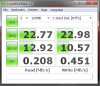
Hi there, I just upgraded my 2710p hard drive to a Pro IV and thought I'd post my results here, they are as follows (btw, i used hdparm to enable udma6 on my little beast):
CrystalDiskMark 3.0
Sequential Read : 87.487 MB/s
Sequential Write : 51.250 MB/s
Random Read 512KB : 84.396 MB/s
Random Write 512KB : 53.569 MB/s
Random Read 4KB (QD=1) : 11.765 MB/s [ 2872.3 IOPS]
Random Write 4KB (QD=1) : 6.971 MB/s [ 1701.8 IOPS]
Random Read 4KB (QD=32) : 24.914 MB/s [ 6082.6 IOPS]
Random Write 4KB (QD=32) : 7.394 MB/s [ 1805.3 IOPS]
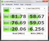
HD Tune: RunCore 32G-C SSD Benchmark
Transfer Rate Minimum : 58.2 MB/sec
Transfer Rate Maximum : 71.2 MB/sec
Transfer Rate Average : 69.5 MB/sec
Access Time : 0.2 ms
Burst Rate : 57.0 MB/sec
CPU Usage : 21.4%
so coming from the 100gb 4200 rpm drive, i am in heaving now!
on a side note, i took the 100gb drive and put it into my aging Zune30 and pumped some life back into it!
very satisfied overall with my upgrade.
My full system specs:
HP2710p
Core2Duo U7600
2gb DDR2 Ram @ 266mhz 4-4-4-12
32gb RunCore Pro IV (i use a 500gb Seagate drive for storage)
Intel 4965AGN (Upgrade from the standard WiFi controller)
Sierra Wireless MC8775 (HS2300 clone w/GSM SIM Pay As You go plan)
That's all i've got for now, lets get some 2710p love here!! i'm tired of only seeing teh 2510p when i do searches on google.
PS I submitted the PLL # to the guys at SetFSB so maybe we'll be able to do some overclocking on this excellent tablet!
PLL: ICS9LPRS355BKL -
Your screenshot here shows byte 9=65 (bit 6=1, no overclocking), so confirms the PLL is TME (Trusted Mode Enable - no overclocking) locked.
INFO: Overclocking
The 2710P PLL is a ICS9LPRS355BKL confirmed here. The 2510P PLL is ICS9LPRS355BGLF. Both of them in the same datasheet here. We see they only differ in their packaging and pinouts. The 2510P is a 64-pin rectangular TSSOP, the 2710P is a 64-pin MLF, yet selecting the 2510P's ICS9LPRS355BGLF PLL in setfsb doesn't allow overclocking. Can try a few other methods to overclock then:
Method 1: Try to overcome the TME locked state, as is done on the 2510PWe can see from the datasheet that the TME workaround that setfsb uses on the 2510P swaps the main clock from PLL1 to PLL3, and the sata clock to PLL2 below. Can perform these steps or some variation of them to see if can overcome TME mode on the 2710P.
Right: 2510P PLL registers before/after setfsb applies TME workaround (OD, OE sets FSB)![[IMG]](images/storyImages/2510pplltme.th.jpg)
Method 2: Overclocking the 2710P by TME-unlocking itStep 1: set TME workaround - 0h(0): 31->37
Sets source for SRC Main from PLL1 -> PLL3
Sets sata clock from SRC_Main to PLL2
- 11h(17): A0->A4
VCO Frequency Control Register PLL3. M Div (5:0)
- 12h(18): 8F->F6
VCO Frequency Control Register PLL3 N Div (9:0)
- 15h(21): 00->01
M/N Enable
Step 2: Set byte 0D and OE manually for your desired FSB
![[IMG]](images/storyImages/2710ppll.png)
![[IMG]](images/storyImages/2710ppll.jpg)
2710P PLL pins of interest: RED=TME-unlock PLL | BLUE=set 166Mhz mode
TME-unlocking the PLL will then allow software overclocking in 1Mhz increments. I *assume* that the you'd likely need to select the ICS9LPRS365BGLF or ICS9LPRS355BGLF PLL in setfsb to do that. Unlock TME by grounding PCI2/TME pin11 as shown here.
Method 3: Hardware Overclocking (Advanced)
The 9LPRS355.pdf datasheet shows that a logic of 1 on the PLL FSLB pin would change the u7xxx CPU FSB to 166Mhz on bootup. You *might* need to slow your RAM's 266Mhz timings to CAS=5 with Thaiphoon Burner as shown here for this to work as otherwise the RAM boots up with the faster 266Mhz timings, yet the RAM is running at 333Mhz.
FSLC FSLB FSLA CPUFREQ
.....0...... 0......1.....133.33 <---- default (u7xxx CPU)
.....0...... 1......1.....166.66 <-----overclock (u7xxx CPU)
.....0...... 1......0.....200.00 <-----default (L7xxx CPU)
.....0...... 0......0.....266.66 <-----b-i-g overclock (L7xxx CPU)
FLSB, pin 64 appears to have nothing connected to it. So not clear if it has an internal pull down resistor. To pull it up would require connecting it to a 3.3V logic point via a 10k resistor, eg: FSLA pin 17 to have hardware overclock to 166Mhz FSB. A successful implementation of this done by tweakertje (though with the 2510P PLL) here.
PLL mod, 200mhz to 266mhz help please thread has more hardware overclocking info.Last edited by a moderator: May 7, 2015 - 0h(0): 31->37
-
these did not work for getting the FSB, so i will not be pursuing it further, this is a work laptop after all, haha
-
Can you post a screenshot of the setfsb->Diagnosis Window? Select ics9lprs355bglf and choose Get FSB. It might be that the individual settings differ somewhat to what the ics9lprs355bglf PLL has set which was designed to support a 2510P.
-
![[IMG]](images/storyImages/setfsb_diag.png)
there's the diagnosis screen
as a side note, i just got a 32gb SDHC card for my 2710, it's one of those $30 ones from ebay from singapore, here's a screeny of the performance on battery:
![[IMG]](images/storyImages/sdcard.png)
some people report problems with the ricoh sdcard reader, only reading at 1mb/s, but that's just what hdtune reads it as, it actually performs much faster
and here's one of the runcore zif drive:
![[IMG]](images/storyImages/sddbench.png)
-
The above poster seems to have chosen the wrong PLL, here is a screenshot of the PLL you requested on my 2710p.
![[IMG]](images/storyImages/setfsb2710.png)
-
What you can say about screen matrix in HP 2710p ?
Brightless, contrast, view angles.
2710p has IPS matrix ? -
2710p compartible with
Toshiba 160 GB 1.8" HDD MK1629GSG ?
http://cgi.ebay.com/Toshiba-160-GB-...emQQptZLH_DefaultDomain_0?hash=item45f148b24f
Disk form Toshiba StorE Steel 1.8" 160GB 4200rpm (PA4140E-1HA6) ? -
Can you attempt to use Overclocking method 1 here, experimenting with individual bits to see if can get a successful overclock by applying the TME workaround?
-
I tried using those settings for both 142 FSB and 150, and each time it remained the same, although some of the hex edits remained, while some did not as seen here.
![[IMG]](images/storyImages/setfsbattempt.png)
-
this drive is SATA and will not work in the 2710p
-
Any news on OC the 2710p?
I've been reading the thread on Linux based OC, but since I don't have windows in my 2710p, I can't even help to find the TME workaround... -
We've discovered that the SU7300-equipped m11x does it's overclock by changing the FSLx pins on the PLL that lead to the BSEL pins on the CPU. THis is somewhat unusual. Usually with non-ULV CPUs, the chipset would lock you to the lowest multiplier if the BSEL pins are changed. Not here.
This then raises the question. Does the same overclock method apply to U7xxx CPUs? To test would require applying a strong pull up resistor (2k) to the PLL FSLb pin (pin 64) to change the FSB to 166Mhz *without* cutting the track. The PLL pinout is shown here. Would then the system boot and run at this FSB?
By not cutting the track, the rest of the system would see a BSEL indicative of 166Mhz operation so would calibrate its other parameters eg: RAM will use 333Mhz SPDTable, X3100 would use the different core/render clock speeds. If the CPU/chipset accepts this altered BSEL without multiplier lockout, it would be the ideal way to overclock.
Only other dilemma is the 965PM chipset officially supports 133/533Mhz and 200/800Mhz operation, though the datasheet does make some reference to 166/667Mhz. -
I have been perusing through this thread and the 2510 owners lounge thread. The overclocking stuff looks quite interesting but tbh the lack of SATA is the main problem I'm interested in solving. To that end I have a 2710p motherboard which is broken (had water spilled on the power regulation circuitry) and seeing as it is already toast I am quite happy to pull off ICs and components to trace the wiring.
Here are some fairly hi-res photos of the board (dial-up alert!!):
http://www.dukeyweb.com/2710p_mobo/P1260299.JPG
http://www.dukeyweb.com/2710p_mobo/P1260303.JPG
http://www.dukeyweb.com/2710p_mobo/P1260304.JPG
http://www.dukeyweb.com/2710p_mobo/P1260305.JPG
http://www.dukeyweb.com/2710p_mobo/P1260306.JPG
I am however a little unsure of where to start with the ICH8-M, I have a rather explicit data sheet for it but it's 500 pages and so far I haven't had the patience to decipher it. Does anyone know if the sata lines we're looking for lead directly to the 82801 IC or is there some other I/O chip I need to be looking into? SMSC KC1070 perhaps? -
See Theory: enabling and connecting to the ICH8M native SATA port. Easiest would be to use a BGA heatgun to remove the ICH8M I/O chip "82801HUB or 82801xxx" and follow the sata I/O pins to nearby vias. If you get the lines figured out, then connect to a sata drive AND you'd probably need to flash the 6710b bios using the emergency bios recovery method to allow it to boot off the sata drive using Windows.
Overclocking update!
Since my last overclocking posts in this thread I've found the SU4100/SU7300 are not BSEL-locked as explained here. Meaning can change BSEL and not get locked to the lowest multiplier. Same may apply to the U7xxx, so could connect the PLL FSLb pin to a 6.8k resistor connected to 3.3V to get 166Mhz FSB. This would be a very clean implementation, using the RAM's 333Mhz SPDTable entry, setting correct X3100 timings as well. -
Ok great, I had already read through all that, I assume then that the NH82801HEM chip is the relevant one? Anyone have a pin out for this IC?
-
It's a large square shaped chip, labelled Intel 82801HBM or 82801HEM. Pinout is shown in the ballout diagram section of the ICH8M I/O datasheet.
-
Hi there,
Is there any way I can help you investigate on how to overclock the 2710p?
I'm using a 2710p with an U7600 and DDR 6400 Ram and could really use the performance increase (1,4 GHZ seems to be no problem...).
So, is there any way I can help you? -
A hardmod will get you an overclock but void your warranty. Simply apply a pull-up resistor on the PLL FSLb pin as shown here to go from 133->166Mhz FSB. SU4100/SU7300 M11x and Asus UL30VT overclocks the PLL the same way which means that likely the U7600 can be BSEL overclocked without being locked to the lowest multiplier. Can also disable TME while at it.
-
So basically, according to this post, I have to sever the contact of pin 11 to the mainboard and have to ground it via a 10k resistor?
Is this enough to overclock, as it seems to disable TME, I guess I can overclock the PC using SetFSB?
If so, is there any disadvantage over hard-overclocking to 166MHZ? -
- setfsb was written for the 2510P's ics9lprs355 which is TME-locked. The 2710P has the same PLL but in the square package which setfsb doesn't work for So to get software overclocking working you'd need to apply the tme_unlock hardmod AND setfsb may require an update. You might be able to overclock by selecting a similar PLL in setfsb's list, eg: ics9lprs365??
- based on M11x/UL30VT overclocks, the ULV CPUs don't appear to be multiplier locked when BSEL mod is applied. Meaning then if you *don't* severe the FSLb pin you are applying a BSEL mod. If it works then the rest of the chipset (RAM, video card, northbridge) is all setup correctly as if a 166Mhz FSB CPU was installed. A very clean way of overclocking requiring no further compensations for timings than expected (eg: RAM SPDtable modification).
- For most flexibility could apply the tme-unlock and FSLb+BSEL mod. If the FSLb+BSEL mod worked, then could still go higher by using setfsb overclocking. If the FSLb+BSEL mod didn't work then you'd have setfsb overclocking to fall back on.
- Numerous reports show a U7600 CPU in 2510P can be easily overclocked to 1.5Ghz (166Mhz FSB) on stock voltage levels. Just need a pioneer to show how it's done on a 2710P. -
Would there be a way to contact you more synchronously?
Like ICQ, MSN, ... ? -
Bump!
Just wondering if you have made any progress on the overclocking... -
Overclocking the 2710P - update
Standard warning: The steps below will void your warranty and could permanently damage your system if performed incorrectly. Please do not attempt the solder methods if you don't know what a multilayer systemboard.
The 2710P schematic, relevant snippets extracted below, makes it very easy to understand what is involved to overclock the 2710P. Method 1 has the advantage of being able to overclock to the point of instability in 0.3 Mhz increments. It is feasible too to combine both. Method 2 bringing the system to 166Mhz FSB, then using method 1 to overclock further if the system is capable.
Method 1: disable TME to allow setfsb software overclocking. [ relevant to U7xxx or L7xxx CPUs ]
Three different ways of doing this with the first requiring NO warranty voiding soldering on the systemboard if done right. You'll know when TME is disabled when setfsb diagnosis window shows the TME_READBACK flag status on register 9 bit6 has changed from 1 to 0, meaning can do software overclocking. Here's a screenshot showing where to look for the TME_READBACK status.
<strike>1. [untested] Jumper the pin2 to your GND pin1 on your debug port (spare unconnected 24-pin socket) to get the PCI2_TME pin to be logic 0. See the debug port layout here. Best done by attaching a 1k strong pull down resistor between those pins to ensure you don't short anything.</strike> Tested and did not work here.
2. Lift one of resistor R279's legs will disconnect 3.3V from the circuit, so that PCI2_TME will now see a logic 0. That means TME mode is disabled and therefore allow setfsb software overclocking. The resistor to disconnect is shown in YELLOW here.
Method 2: Set PLL to run at 166Mhz [relevant only to U7xxx CPUs ]
Just lift a leg from R197 to disconnect the PLL from the circuit, then route it to a 3.3V point at R195. sendig a logic 1 to the FSB pin, setting the PLL to run at 166Mhz. So a U7600-1.2 will now run at 1.5Ghz. The resistors are shown in here.
* EXTRA: CAS=5 in the 266Mhz SPDtable RAM entry for higher levels of overclocking[/B]
I found on my U7600-1.2 (133Mhz FSB) 2510P sees ~177Mhz FSB to be the cut-off point where the RAM timings start causing system instability. The way to correct this is to increase CAS from 4 to 5 against the 266Mhz SPDtable entry. That can be done using Thaiphoon Burner as shown here or with SpdTool.
Method 3: Set PLL to run at 200Mhz [ relevant only to U7xxx CPUs ]
More details about this are in the 2510P 200Mhz_bclk link. This will run a u7500/u7600/u7700 at 200x6 instead of 133x8/x9/x10 for faster RAM and X3100.
Just lift a leg from R829 and R834 will disconnect those parts of the circuit and send a logic 0 to the FSA and logic 1 to FSB, setting the PLL to run at 200Mhz. So a U7600-1.2 will now run at 200x6. The resistors to disconnect are shown here.
Softmod instead: dual-IDA bios mod
This is not a hardmod in the sense that a modded bios flash is involved instead and use of Throttlestop software. See http://forum.notebookreview.com/hp-...0-6910-6710-6510-27x0p-25x0p.html#post6654683 . This may be preferred by those that do not want to void their warranty. Eg gains to be had:
U7600-1.2@x9 -> 1.33@x10
U7700-1.33@x10 ->1.46@x11
L7500-1.6@x8 -> 1.8@x9
L7700-1.8@x9 -> 2.0@x10
Conclusion
Combining method 1 OR 2 AND the dual-IDA bios mod would give the maximum overclockability possible.Last edited by a moderator: May 8, 2015 -
I think if I had to do one mod, this would be it, provided there's easy access to the R279 resistor.
Could I use grub2-setfsb to get it working on Linux?
Is there any Linux tool that would allow that?
Could you please maybe identify based on these photos where the marked resistors are?, that's it, if you know where to look for them.
Thx!Last edited by a moderator: May 8, 2015 -
Once setfsb supports your variant of the ics9lprs355 then it is very easy to just update the grub2-setfsb's ics9lprs355.c as explained here to overclock your system to whatever level you wish.The resistors will be near your ics9lprs355 PLL, location as shown in RED in the picture to the right.
Keep in mind that setfsb's ics9lprs355 support was written for the 2510P which unusually allows it to be overclocked even with TME enabled but will not do the same for the 2710P. Only difference is the 2510P has a rectangular ics9lprs355, the 2710P has a square one.
That means you'll only know if the ics9lprs355 in setfsb will work with your TME-unlocked PLL. If not then you may need to email the author of setfsb to get support for a TME-unlocked ics9lprs355.![[IMG]](images/storyImages/2710ppll.th.jpg)
You'll need to do your own research RE: Linux tool to write RAM spdtable. You could just remove your RAM modules and write to them on a friend's WinXP/Vista/7 system using Thaiphoon Burner.Last edited by a moderator: May 7, 2015 -
when i try to install a chipset or video driver, a message "your computer does not meet the minimum hardware requirements" comes out.
why? how can i bypass this? -
UPDATE. You have an unconnected 24-pin debug port near the fan controller. Above I've explained that that jumpering the debug port's pin2 and pin1 (GND) will disable TME mode.
-
The dual-IDA bios mod has been done for the 2710P: http://forum.notebookreview.com/hp-...ios-8710-8510-6910-6710-6510-2710p-2510p.html . Biggest % increase in performance is seen on L7500 systems.
U7500-1.06 -> 1.20@x9
U7600-1.20 -> 1.33@x10
U7700-1.33 -> 1.46@x11
L7500-1.60 -> 1.80@x9
L7700-1.80 -> 2.00@x10
Can a 2710P owner please test to confirm success and post their dual-IDA wprime 2.0 32M and Win7 WEI score improvements? -
any help?
this is not an "only who to overcl. the cpu" thread! :S -
I've just finished jumping pin1 and pin2 soldering the resistor. I'll try to get a windows in the laptop somehow to test if it can OC using setfsb or directly test grub-setfsb, I'll have too look into that.
I think tomorrow I'll flash the IDA bios as well. -
I wish I could help you (linux user), but this seems like some kind of windows error. Shouldn't you be trying to ask the same question in a windows software forum in this same board?
-
You'll know if jumpering those pin1+2 on the debug port has disabled TME by checking if the TME_READBACK flag status on register 9 bit6 has changed from 1 to 0, meaning can do software overclocking. Here's a screenshot showing where to look for the TME_READBACK status.
If you're pulling your system apart you may want to also do a hardware undervolt by using a conductive pen to bridge VID3, VID2 and VID0 cpu or voltage regulator pins as explained here and posts after it. -
Well, I got it to boot native the windows 7 partition I use in Virtualbox.
setfsb shows H'65 in 09h and H'FC in 02h, so I guess this is that the mod didn't work.
I'll open it again tomorrow since the keyboard is behaving. Some keys don't work, so maybe the flex wasn't well fitted.
I'll take a photo of the SMD resistor I soldered so you can assess everything is ok.
I'll try to check how to access the voltage regulator. Getting to the debug port was really easy, as removing the KB gives access to it. If it doesn't require tearing apart the whole MB I might do it. -
I jumpered debug port pin1+2 on my 2510P and it didn't disable TME either. In which case can use the second method to disable TME:
2. Lift one of resistor R279's legs will disconnect 3.3V from the circuit, so that PCI2_TME will now see a logic 0. That means TME mode is disabled and therefore allow setfsb software overclocking. The resistor to disconnect is shown in YELLOW here. -
Hi!
I've recently updated my 2710p with a 64gb runcore ssd, and i've made some benchmark before/after:
Win 7 scores:
Before
-------
CPU 3,9
Memory 4,2
Aero 3,1
Directx 3,0
Hdd 3,9
After
-------
CPU 3,9
Memory 4,3
Aero 3,2
Directx 3,0
Hdd 6,3
Crystal Diskmark pictures below.
I tried the dualIDA bios, but unfortunately it didn't work I flashed 2 times, but no change. Battery bar shows the same 1.2ghz, win7 scores the same and wprime too...
update: I restarted it, and now i got 4.1 for CPU score, wprime went down to 72 sec from 78.
But i'm happy with the ssd, my laptop goes so smooth I love it.
Attached Files:
-
-
Need to install Throttlestop, right click on it and select "Start Dual IDA". Appears you've figured it out.
The SSD makes a big. ProIV set a new performance standard, with the Renice K3VLAR ZIF SSD taking it one step further. It uses the faster and more compatible Marvell sata-to-pata bridges. It's cheaper too: 32GB is US$120, 64GB is US$200, 128GB is US$380. -
Does anyone have bios for 2710p that would have both Dual Ida and Whitelist removed mods?
I would really appreciate it. -
(why can't I delete the message completely?)
-
bump.
So no one really has this kind of bios ready at their hard drive? -
Right, I have removed the NH82801HEM package from the faulty motherboard (hey - it only took me nearly a year to get round to it, things are improving). I have also looked through the supplied datasheet and found the following relevant pins:
SATA_CLKN: AB7
SATA_CLKP: AC6
SATA0RXP: AF5
SATA0RXN: AF6
SATA0RXN: AH5
SATA0RXP: AH6
I also found these, are they necessary?
SATACLKREQ# / GPIO35: AG13
SATA0GP/GPIO21:
And I located the SATA LED pin: AF10 (probably won't use this).
So the next question is, how does the figure relate to the actual chip. Does the figure represent the chip as you would look at it so the writing is the correct way up? I'm presuming "top-down" means looking from the side of the writing? -
You might want to post here:
HP Elitebooks - Tablet PC Forums, Discussion and Support
since it is a forum devoted to tablet PCs. Good luck. -
The SLIC 2.1 + no-whitelist + dual-IDA modded 2710P bios is now available: http://forum.notebookreview.com/hp-...0-6910-6710-6510-27x0p-25x0p.html#post6654683
-
is it possible to use the 2710p only with the slim battery? (without the normal battery)
thanks -
Yes it is.
At least it boots up fine and should therefore work
-
I completed a long overdue windows update at the weekend on my 2710p. One of the updates was new graphics drivers for HP.
After the update I have lost the native resolution and am stuck with a max resolution of 1024x768.
The tablet was due a reinstall anyway which I duly did with no effect on the resolution. This was done from the recovery partition.
As I also have the docking station and the correctly supplied recovery discs, I decided it would not be too much hassle to reinstall from this option as well.
The same result...Resolution stuck at 1024x768 max. I have tried updating with the previous drivers. No joy.
I am now stumped. Anyone any ideas? -
Tried this, disassembled my 2710p, but there was no resistor on R197. Only the cooper plates, to solder something on the board.Last edited by a moderator: May 8, 2015
-
Had a confirmation that jumpering the debug port's pin1+2 on a 8710p here did TME_unlock the PLL so setfsb could program it. Please try that first.
*HP EliteBook 2710p Owners Lounge*
Discussion in 'HP Business Class Notebooks' started by bigted, Feb 22, 2010.

![[IMG]](http://img4.imageshack.us/i/2510pplltme.jpg/)
![[IMG]](http://img689.imageshack.us/img689/7660/2710ppll.jpg)


![[IMG]](http://img685.imageshack.us/i/2710ppll.jpg/)