
I want to start a new thread about replacing the stock panel of the 2530p by another screen. Since none of the stock panels are very interesting, this improvement will not be as simple as just a plug and play replacement.
Such swap was tried 3 years ago, here, but was never finalized due to connectors differences.
I spent a lot of time to understand the differents panels and options that come with the 2530p.
First of all, I must say there are basically four different panel assemblies. For each assembly, a different LCD cable must be bought. These are :
All the 20pins panels have an inverter outside the panel. The 40pins seems to have the inverter board merged onto the panel's mainboard so that only one connector is used to link the LCDscreen to the laptop's mainboard. I found that the following panels may be encountered inside 2530p laptops (+ maybe others) :
PN conn. type Webcam DC02000LZ00 20 no DC02000JM00 20 yes DC02000WE00 40 no DC02000WF00 40 yes
The last one seems to be the only 40pins LCD panel that I found to be sold with some 2530p. Panel names on this table are linked to their respective datasheet. The good new is that the interface connector type and pinout is always fully described !
manufacturer ref. viewing angles luminance contrast ratio con. type Samsung LTN121W3-L01 45/45/15/30 220 cd/m² 300:1 20 pins + 7pins AUO B121EW07 40/40/20/40 200 cd/m² 400:1 20 pins + 7pins Toshiba LTD121EW7V 30/30/10/20 200 cd/m² 500:1 20 pins + 7pins AUO B121EW09 V2 30/30/10/20 200 cd/m² 500:1 40 pins
Like the old thread, the best candidate may be the AFFS Hydis HV121WX5-110
This screen represents a good improvement over stock panels and can be found for around 40€. Usually, it comes from HP 2170p and 2730p laptops. The hydis HV121WX6-XXX is also compatible. It is found inside Lenovo X200T but is really too expensive.
Hydis HV121WX5-110 80/80/80/80 220 cd/m² 500:1 40 pins
There is also this one :
This screen is also found in HP 2710p and 2730p laptops. It may be a much better replacement (MVA type, better contrast), but it seems that the inverter is not built-in (or it is an error inside datasheet since it is a 40pins connector with LED backlight). This one is much harder to find and much more expensive too. Its 40pins connector is the same than hydis one but pinout is slightly different.
ChiMei N121I7-L01 85/85/85/85 220 cd/m² 800:1 40 pins
The S-PVA Samsung LTN121AP03-001 display may be another good candidate, but I wasn't able to find any datasheet.
So, I think the best candidate is still the HV121WX5-110 (AFFS type). In fact, any HV121WX5-XXX would be OK, the last three numbers are only for a different manufacturing batch of the same panel.
I bought a DC02000WF00 2530p LCD cable and a 50.4Y817.001 rev A01 LCD cable that fits 2730p laptop. I received the last one yesterday. The goal is to use the the 2530p's cable with the 2730p LCD connector.
Here are these two cables :
some quite simple reverse engineering using a multimeter and the 2530p schematic (found here) allowed me to verify electrical connections through both LCD cables.
The 2530p DC02000WF00 The 2730p 50.4Y817.001 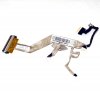
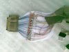
The following photo represents the two LCD cables (2730p on the left). The connectors has been opened to see how wires are soldered to the connector. The 2730p LCD cable is very high density. Soldering will be very tricky !
I have identified the labels of each pin of the 5 connectors attached to the DC02000WF00 cable. With the pinout of the HV121WX5-110 LCD panel, it's very easy to build a wiring diagram. these data are summarized into this file : LCDpinout_2530p.ods. (a libreoffice calc file - it is writen in french, sorry by that )
Work in progress...
-
Is there anything new?
If so, the two cables connecting to ask me a wiring diagram? -
Not yet finished (I had no time to do this up to now), but I will upload a wiring diagram asap.
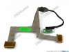
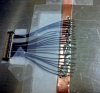
The main difficulty comes from the 2710p LCD cable. All the blue wires (see the last photo of the 1st post) going to the high-density 40pin connector (on the left of the photo) are coaxial !!
Yesterday, I spent around 1 hour to separate gnd from signal for only one wire. Each wire has a diameter lower than 1mm. Up to now, I'm just training to do it faster before managing all the 21 wires. -
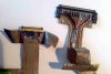
The cable is almost finished. Here is a photo of it :
A quick photo of the work in progress. All the grounds of each coaxial wire have been attached to an adhesive copper tape.
The work was not easy at all. I had to use a binocular microscope, a surgeon cutter and other high-precision tools.... I was also very happy to have a Weller station with a WXMP "pencil".
The metal-frame surrounding the LCD panel had to be thinned on its top to fit inside the cover. It implies a complete disassembly of the panel...
First test : the screen <strike>seems to</strike> works like a charm ! <strike>I can see the bios menu when the screen is highlighted using a headlight but the LCD backlight remains OFF</strike>.
The LCD cover I ordered has the ambiant light sensor option. There is a small PCB under the panel that drives the LCD PWM brightness control. <strike>Now, I need to understand how it works because AFFS LCD panels are normally black contrary to TN panels.</strike>.
Edit: everthing works now. The backlight was not connected to the LCD electronic board. -
Today, I'll do it, thanks for the pics! I will write. -
I put some more details on this mod here.
There is a really huge improvement against stock panel. 2710p and 2730p Hydis panels can be found for almost nothing on ebay. It's a chance. I will take some pics of the new screen vs. old one soon.
HP Elitebook 2530P: Screen Swap 2
Discussion in 'HP Business Class Notebooks' started by Xtof, Jun 15, 2013.
