Forgot to mention yes it was working and my mapping software recognize it but I could not get a fix on any satellites. Then my night went bad with after I hit the wrong button in SirfDemo.
Jim
-
Thanks guys... I was up until 3 am fooling around with it. I am having my first cup of coffee and will go down in a few and try Cadillac's wiring diahram. Do I need a good shot of the sky to get data????? I would think I should see data streaming regardless...
-
Modly... All you need to do is grind away a spot to mount it. BUT BE VERY CAREFUL!!! Magnesium burn VERY hot if ignited!!! I doubt you would set the whole lid on fire but the shavings are VERY flamable if lit with a spark!
I think the guy on ebay heats the corner piece and bends it to shape. You'd probably need a form. Then... Heat it up and press it into place. -
Toughbook
Yes you will get a data stream from the module but remember I had to remove both com ports in the device manager and reboot before my software would see it. You might have the same problem.
Jim -
Toughbook; I'm aware, two of our dry grinding machines at work instruct to never, ever, ever even think about touching magnesium parts to the machine, and that it will give me terrible crotch rash if I think about it, then it'll tell the guy at McDonalds to put cheese on my quarter pounder... That's how bad it is.

You won't need a clear shot of the sky to get something out of it, it's just gotta be attached.
Cadillac, I've actually done that before with my in-car module, and it took me a few minutes to figure it out. What you'll have to do is figure out what baud rate you set it to, and re-open it with that. If all else fails, just try connecting to your COM port, and try all the baud settings. If you have the wrong one in SirfDemo, it just won't connect to it. -
Hmmmm... I was thinking the guy must have made a mold and was molding new corner pieces. Your idea sounds a lot more feasable! Still though, they look so perfect in the picture, better than what I would think you could achieve by just heating it up with a heatgun and forming it around a mandrel. Wouldn't that pull the screw holes off location, requiring you to drill new ones? It didn't look like he had to do that.
-
He may have cut out a chunk in the magnesium, screwed the rubber piece into place, set a mandrel down, heated the rubber, then pressed it...
Or I'm overthinking.
Either way, I really don't like his location much because of what is right behind it under the bezel. That location would set you right into a LCD bracket. -
I personally don't like it because I'd break the antenna off. I do admire the stock-looking appearance though.
Here's my idea. The EM-408 claims to have a built-in "patch" antenna, looking much like the stock GPS antenna. I wonder how much Heartland charges for the plastic corner piece for stock GPS? Hopefully just the plastic piece wouldnt' cost much. Given that, can't we stuff the EM-408 up in there? We could then bring the external antenna jack to the back panel and have the best of both worlds. A low-gain "better-than-nothing" antenna for when we're just carrying the notebook around, and an external high-gain antenna for rooftop mounting or whatever.
Just a thought, what do you guys think
-
I am getting nowhere with grinding a hole in the top. The curves of the upper piece will make it so it does not sit in place.
I'm looking at another idea, but it's not as good or easy sounding, but making a custom side piece out of steel. It'd be a two piece setup, but might end up being easier for retrofits if we had a way to produce them. -
Hey guys magnesium is not much different than aluminum when working you really can’t grind either with standard wheels “they just load up” and for this application I would think using a carbide on a small die grinder or Dremel would be your best bet. They do make special tools for this that has wider flutes but I don’t think it’s necessary unless you plan on doing several. You can also just run your carbide through one of your wife’s candles before you start grinding and you will be fine.
It takes a lot to start a fire on the solid part but not much for the grindings so be mindful of the pile of grindings and keep your area clean probably best done outside and remember if is dose start on fire don’t try to use your beer to put it out it will only make the fire bigger and waste beer.
Jim -
I use my Dremel tool and a toothed grinder... It works fine. I go slow, and as Cadillac points out, keep my area clean and don't let the shavings build up. (Actually I end up pputting them in a small pile and then light them!
) Yes... I'm a pyro!
I would think the best spot would be where the RIM antenna goes. It would take minimal modification. You would just need to mount your wifi antenna in another area.
Modly... Can you please post a wiring diagram for the antenna? I am pretty sure how it goes but want to be sure.
I'm going down now to take my measurements and maybe resolder a few things. -
I made the hole fine and dandy with the dremel, but the problem is the curve in the upper lid, so it won't end up clamping down. Of course, this is on my "parts" book, which had a cracked 12" screen, so I don't mind it being tampered with... but it's still slightly annoying that I can't figure a way to mount this puppy. In all honesty, I think the guy on eBay probably has some really nasty looking setup underneath the rubber, but without looking at one, who knows.
If I could find a place to set this thing in, I could take the lid to work and set it in the bridgeport and really go to town...
I'm gonna try one more idea though. Back in a bit.
Edit; I don't have the wiring diagram for the antenna, I was gonna look it up later. If all else fails, I can call Jim D Gray. Those guys seemed very anxious to make weird things work. -
Okay... I have it working now... kind of. I uninstalled the Com ports 1- 4 and then rebooted. Then it came up. Before I turned it on I was showing 2.8V at pin 1. When I turned it on the voltages jump all around... From 1.4V to 2.8V and then all over the place in between. I'm assuming it corresponds with the data stream.
Should I swap pins? I am showing 4 satellites but they are not in the green and I don't get a fix.
What to do.... -
Congratulation Toughbook now you are smelling what I’m stepping in.
Sounds like it’s working to me.
I don’t think you need to change any pins just configure the software -
Modly... Here is the antenna nomenclature....
http://home.comcast.net/~Toughbookhack/geohelix-s.pdf -
Nice health warning, would make a great safety video
Would have to use fake beer though...
Cant find the one on that one on ebay with the black lid, found one with a red lid with google that's not as clean looking though. 1300?? 13f'ing00??. My good god.
Anyway. That one looks like the standard corner piece has been heated up and moulded around something about the same size. Must have had to cut lumps out of the LCD frame and the electrical noise around that can't be doing any good.
Other than laying it flat around the latch or a 'power bulge' type thing on the outside of the lid I can't see anywhere it will go in nicely and be fairly well protected.
cheers -
Caddy... Nah... It's not working well... It should be picking up all sorts of stuff. When I use the Globalsat utility it picks up 4 satellites but I still don't get a fix. When I use WinFast it picks up anywhere from 1 to 4 then back to 2. But then it could be that the patch antenna that it comes with is not that good. I need to figure out the wiring for the active antenna and then do that up. Modly... Lets get the antenna working forst and then I'll figure out how to mount it.
EDIT::: Yippee... It's working... When I went back I had 8 satellites with 5 in the green and have a good lock!
Thanks for the help guys! -
Now we need to figure out how to do this without the board!
-
Well, if the data stream works, the best way to test is to get an antenna working, because I believe it just can't get enough signal through the magnesium.
I didn't test mine for a fix yet either, which I should probably do.
I did work on a way to mount the antenna though, which may or may not work. It's how I'm assuming the other guy does it.Attached Files:
-
-
Working on it!:wink:
-
Modly... Stop.. Take the board out of the laptop and then just ground it with an alligator clip lead. (That's what I did) I wanted to make sure the board was out of the laptop with the antenna pointing up. I'm up to 6 sats in the green now!
Okay.. I'm in my shop now and have the antennas. I don't mean to sound ****y but whatever the guy on ebay can do I can do better! The antenna would be a perfect fit in the RIM location with just a little dremeling. But he has his on the other side. I've got a cover out now looking into it...
EDIT - Caddy... did you buy the same antenna? -
In my location, you need to cut out a small chunk of the rubber LCD backing, and I'll have to trim out a little bit of the LCD bracket.
-
Guys.. I just imported on of that guys pics into Photoshop and blew it up... He's just cutting the plastic and folding it back a little... Like I said.. Not good... We can do better.
-
Could you cast a new corner piece from a 2 pack cement? I'm not sure if rubberised ones exist, all the ones I have seen set hard. Looking for something similar for a normal antenna mount.
EDIT. the antenna could be embedded in it for mounting. -
For me.. It has to look stock... I'll figure it out eventually.. I still think the form, heat, bend method would be the best bet...
EDIT - But we could use JB Weld on the inside to secure it or to even out the interior... -
I'm finally getting this thing to fit pretty well on my 13", now I gotta make a hold down bracket. That's gonna be the hard part.
I'm still thinking that perhaps a side mounted antenna in the stock location might be our best bet, at least for "mass production", but who knows. I'm still working on this idea. -
Hey could one of you guys that have the GeoHelix antenna just duct tape it to the approximate location on the back of your Tough book and drive around in you car and let us know what your reception looks like?
Me thinks lets see if this antenna module combination works first then make it perddy!
If it works good then I will have some bit chin parts machined and supply you with one. -
Modly... Funy that you mention that... I was just surfing the web for that very thing. I think with the power of this GPS we could use a patch antenna stuck to the side of the plastic cover (opposite LAN & Modem) and it would work fine. Either that or a passive antenna instead of an active one.
-
I wish I had some thicker gauge steel on hand, so I could make a bracket... I'm out of metal thicker than 22g.
Edit; Does Heartlandsi have those GPS lumps for sale? -
Modly... I just finished modding my lid... Looks similar to yours. I think I'll try what it looks like the guy on ebay does. You can't fit it all the way down into the lid so use a fat rubber "O" Ring to close the space. I am using a 7/16" ID o ring to close the gap on mine. But, like you, I need to mount it.
So.. Having looked at the eye wash for the antenna... Ground is easy to figure out but what about power and signal. It's not clear which is which. Or does it matter? -
Are you starting to see why this guy gets the big money?
-
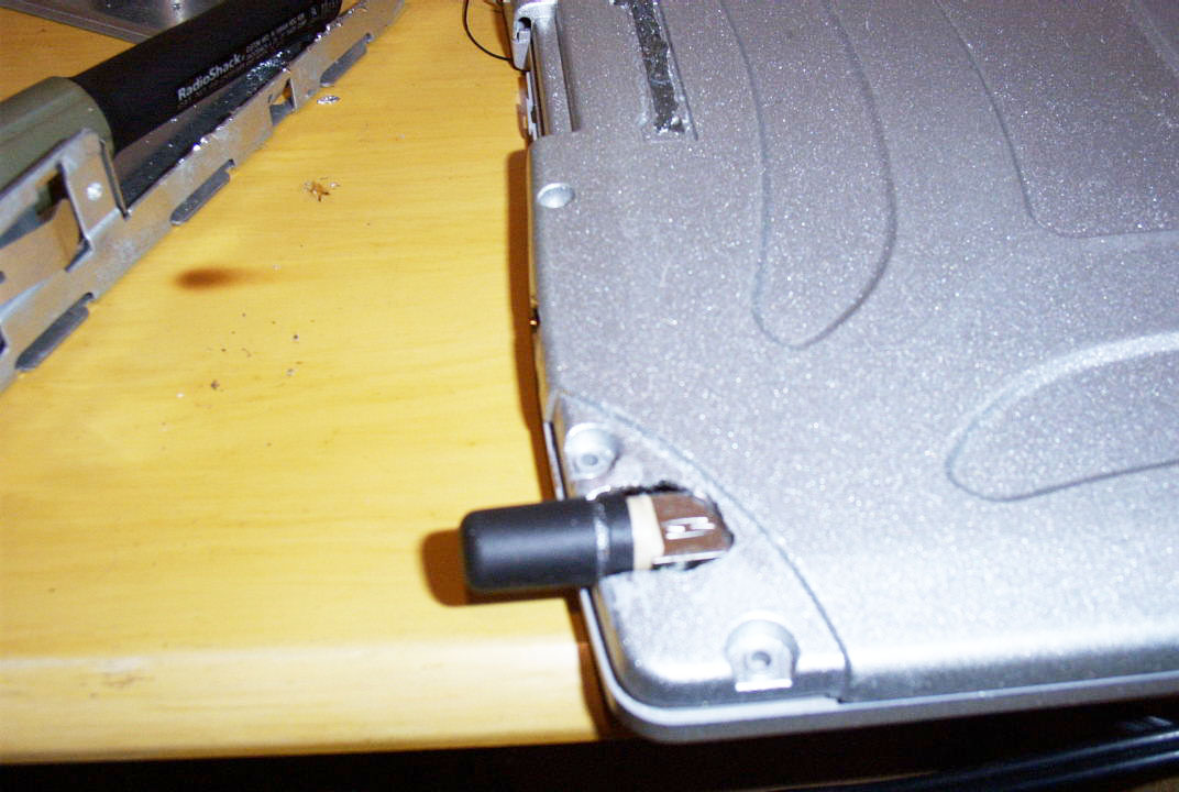
Okay... Here's my mount. Note the O Ring on the base... I think that with the antenna base in the same plane as the body of the lid that it should fit with little effort. The rubber then will not need to be bent... as much. I think I could trim it to fit.
I just need the connections...
![[IMG]](images/storyImages/gps.jpg)
-
He does a ton of custom work, but the big money comes in with the GPS. I noticed that books with wireless built in also score another $100 easy, compared to non-wireless counterparts.
If we have a toughbook with wireless, and built-in GPS, they will go for a ton on eBay. -
Since you cut that portion of the lid, why not just stack the patch antena on that location and then put a sealant then cover by that black plastic and it is more stealth looking, how's that? and then at the other side will be the wireless antena that mostly notebook used.
-
Problem is, Patch antennas must face up. They have a very limited angle that they can use for scanning satellites, and if it's not directly up, you may not see them.
-
I got my antenna to fit and the rubber piece to fit around it. If I can get it wired I can then think about securing it in place. With the magnesium around I was thinking about soldering what I need... Testing it and then sealing the base of the antenna in a rubber coating so the contacts couldn't/wouldn't short out.
Any connection ideas? -
I dont have the original stack gps of cf-28, may i know the position of the orinal patch antena? the one with a bump. Thanks
-
The original patch antenna is inside the bump...
-
Ohlip, the stock GPS patch antenna has the bump facing upwards through a few pieces of plastic. It's range was limited for scanning because it is set about 1/4" lower than the keyboard deck, so the magnesium blocked some of it's ability to scan the sky.
Toughbook, Good job on getting it in place. I'll look up the connection a bit, and see what I can figure out.
Edit; It looks like the small notch on the bottom is where we attach the power, and ground the 4 notches on the side to our RF shielding.
I wonder if Jim D Gray sells connectors for these puppies... -
They don't sell connectors... I asked. He was VERY specific about soldering these. It must be done VERY quickly to avoid melting the board and contents.
EDIT - His tip was to presolder the wires to be attached and to very quickly presolder the tabs.
So... Must all 4 Grounds be connected to ground or just one? It says in the antenna manual that the DC-IN and RF-OUT are the same connection. Does that make sense? -
It shows that the ceter should be soldered with both DC and the RF.. But there are two copper spots on the back that the manual doesn't mention...
-
It might work on reverse polarity or something. He gave me the same lecture on soldering as well, so I gotta wait for my new station (I did the boards with a pencil, and hated it).
I'm not sure exactly how the antenna soldering should go, so perhaps I'll need to make an X-wire setup to connect all 4, then solder a lead from that.
Either way, I'm out of the antenna game til my soldering station arrives from Kansas... because I'm sure my beat up pencil will destroy those antennas.
Edit; I was wondering about those flat spots on the back too. Tomorrow I'm gonna call Jim D Gray, and see if they have any input about those.
As for DC and RF, the RF signal provides 3.3v DC. -
Okay... I looked again. The spots on the back are called "Ground Pads". All four spots and the two on the back are grounded. The multi-meter proved that.
So... I guess I need to start up the GPS and take measurements from the antenna to check for voltage, yes? The center lead should be the RF+3.3V? I got ants in my pants bro... I gotta keep trying.. I'll keep you posted. -
Yes, I believe the center pin on the MMCX is +3.3v, and the outside is the ground. I haven't verified polarity, but logically it makes sense (Being that you want ground as your shield). I'd check it just incase though.
I know what you mean about the ants in the pants though! -
Okay.. The outer shielding is ground and the inner is the RF + Voltage. However... I am reading a steady 2.8V on the center conductor. I've just soldered everything up and am going outside to test it.
Keep your fingers crossed! -
I'm hoping it works!
With luck, I'll get mine soldered by wednesday. -
Bada Bing Bada Boom
![[IMG]](images/storyImages/gpsresults.jpg)
Works like a charm.....
I'd like to thank the Academy....
Seriously guys... I really wanted this bad... I appreciate everyone's input on this... I LOVE IT!!!
Like I said... Now we need to be able to hook this up sans main board...
I'll be spending the rest of the night and tomorrow getting the antenna mounted. I'll post pics when I do...
EDIT - By the way... It is sitting on my kitchen island... I lost just one satellite and am STILL getting a good, strong signal! -
This is incredible.. I am in my shop... In the basement (No windows!) and am getting 8 satellites. Not realy strong signals but enough to get a fix. This is just incredible. If anyone else would have told me this was possible I'd be inclined to call them a liar... Or at least stretching the truth.
Now I have 9 satellites.
I just picked the laptop up and walked across the length of my basement. It actually registered my speed as 3KM/hr!
Just incredible...
I'm starting to think that if we had an active antenna that we could hide that we could just keep it in the case instead of mounting it on the LCD... I'm going to try taping the antenna to the insside of the plastic cover and see what I get.
EDIT - You get nothing with the antenna insude... It just wasn't made for that. No sats at all. -
what do you guys think about my stock-GPS-plastic-bump idea? Unless of course they're unavailable or too expensive..
-
Toughbook
Thats great! I think I will have to read this post with a fine tooth comb! I seem to rember a member posting a link to a small active antenna, I think it was over $60.00 or so. Do you think that using the gps set up on a 800mghz machine would be ok. My 28 has 512 of ram and a 40gog 5200rpm drive?
Adding Aftermarket Internal GPS to the CF-28
Discussion in 'Panasonic' started by Toughbook, Nov 19, 2007.