thanks for share the picture
can you move black cover in the last picture ,i want to see the pcb.
i want to confirm the 24 pin dock connector
base this link
http://forum.notebookreview.com/thr...-dock-internal-pictures.828478/#post-10897353
24 * 23 * 22 * 21 * 20 GND 19 USB3DMRX 18 USB3DPRX 17 GND 16 USB3DMTX 15 USB3DPTX 14 GND 13 USB2DM 12 USB2DP 11 GND 10 5V 9 5V 8 5V 7 16V 6 16V 5 16V 4 GND 3 * 2 * 1 *
*is unknown and i have no hardware to check dock connector is right or wrong
and 22 & 1 maybe is short to gnd ???? to let 5v & 16 out & in. i think ???
so i need your picture for confirm which one
-
this link is a picture
is there anyone can help me upload this picture
https://photos.app.goo.gl/otVp6xHUKM2RJRpJ9
maybe short to gnd to switch the power on/off???maybeLast edited by a moderator: Jan 11, 2020 -
The keyboard has been re assembled and would need to be taken apart for any other photos.
Not really a pcb it is just the connector if I remember correctly.
Here is your photo.
-
OK
THANKS
I WANT TO CONFIRM 1 & 24 WITCH ONE IS CONNECT TO GND ,AND ANOTHER ONE IS USE TO WHERE
CAN YOU DO ME A favour,if you have a time
thank you a lot -
-
ok . thank you for your help !!!!!!
-
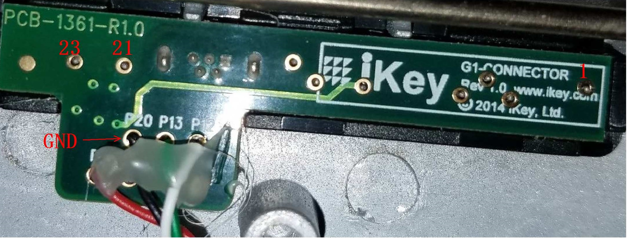
These?
-
[QUOTE =“ Shawn,post:10983749,member:312530”]这些?
[ATTACH = full] 181559 [/ ATTACH] [ATTACH = full] 181560 [/ ATTACH] [/ QUOTE]
thank you very much
can you help me take some the pcb other side picture.
It's two layers pcb
I can't confirm the first one and the last one use for what
Thank you for your helpLast edited by a moderator: Jan 15, 2020 -
That is the best you are going to get.
The board appears to be molded into to the other half of the black connector.
If it is not molded it is stuck down very tightly.
I am not willing to apply force and possibly break my keyboard.
You may want to read the following thread.
http://forum.notebookreview.com/thr...-dock-internal-pictures.828478/#post-10924257interestingfellow likes this. -
ok thanks
do you have a multimeter to test pin 23,21,1is short to GUD????Attached Files:
-
-
I have 4 multimeters. One for each hand.
 .
.
Multiple multimeters help me multitask multiple problems and multiply my efficiency.
I will ring those pins and post the results for you.interestingfellow likes this. -
thank you
I'm so lucky,
-
pin 21 shorts to ground.--p20 terminal
-
ok thank you
i made a mistake
p20 is pin 21........
p22 23 is pin 23.......
pin 1& p20 is short or have
resistance ??
and pin 20 & pin 22 have resistance???Last edited: Jan 16, 2020 -
Why do you need all of this information?
What are you trying to build?
I want more information before I do any more testing.
Please ask all of the tests you want in one post.
I have taken this apart 3 times now. I am getting frustrated taking it apart for every new post.
P20 and pin 1-- I tested with continuity setting on meter.
The tone sounded indicating continuity between those 2 pins.
The other 2 pins you marked did NOT have continuity with P20.
No other tests were performed.
I did NOT check resistance value between any of the pins.
There is no P22 or P23 marked on the board.
The pins on the board are marked in white, P20, P13, P12
I am confused as what pins you want tested?
UNCNDL1 likes this. -
I'm so sorry for you feel confuse
Fz-g1 have this 24 pin connector for docker
, this just is a USB 3.0 port.,base some picture, your ikey keyboard is a USB 2.0 keyboard,I think so,but there is a problem, I don't know how to let fz
-g1 output 5v power source,,I use multimeters to test ,there is no 5v
Out,so I think maybe there is any pin(P22??P1??? P24??) short to gnd or resistance to gnd to let fZ-g1 output
5v source.
P1 and P22 is unknown use for what
Maybe P1 is shield,
Thank you for your help,and take your time.
fZ-g1 only have one USB 3.0 port,
I want to make a pogopin pcb to add one USB 3.0 portLast edited: Jan 19, 2020interestingfellow likes this. -
i think 24pin connector is a usb 3.0 port and 16v power source
vebg11 is a usb hub
use smsc chip which is have 4 usb3.0 port and 3 usb 2.0 port
one usb3.0 port is for display link chip(hdmi&vga) and another one is for laninterestingfellow likes this. -
I added the usb 2.0 port to the card reader connector beside SSD. Simple and very easy to do.
Instructions are in this thread.
Panasonic docking ports usually do NOT have B+ voltage to them. The docks all have external power supplies.
On my next photo
G / P10 will most likely be the only B+ voltage you will find. I am betting that is low amperage. Just enough current to run the keyboard.
interestingfellow likes this. -
还有一个问题,如何让
ikey keyboard have a battery inside,you need charge, fZ-g1 can't output any power source ,wtf , I think so, because fZ-g1 is a IP65 protection, at first is think fZ-g1 is out put.5v . maybe it's wrong...
Thank you so much -
The newer iKey keyboards do not have a battery; they are powered through the USB connection and have a USB port on the side. The FZ-G1 docking connector contains a USB-3 pass-through. My Havis FZ-G1 docking station has a 16 V power connector for an external power supply. I don't know about other brands.interestingfellow and Shawn like this.
-
-
thanks ,i know that ,so I think maybe dock
Connector is short to gnd for output 5v power source,It seem to a wrong -
Correct. I have 2 iKey keyboards. One has a usb on the side and one does not. The one with the usb is lighted while the other is not. The non lighted does NOT have a battery.
-
I need to get home to my DMM and my vebg11 dock!
Thank you Sxueshu for your interest and work and
Thank you, Shawn for all the work you have committed!Shawn likes this. -
but usb3.0 pin not confirm yet,
It's just a guess I base you picture &USB hub chip.
I'm working a pagopin pcb with a USB 3.0port , after confirm, I can tell you what I confirm.
I want your vebg11 docker pcb front &back picture without ffc cable, if you are easy to take some picturesinterestingfellow likes this. -
I'm in the same boat! Installed the LAN port but it doesn't show the ethernet adapter in device manager. Would you be able to relay how you managed to clone the bios to get it working?
-
Unsolder BIOS chip of the source device - save it's contents to PC - unsolder BIOS chip of the target device - program it with the file saved - solder the target chip - check if it's ok - solder the source chip back.
Cold start delay is veeery long. I will not do this cloning again with FZ-G1. CF-19's are ok though.
You need a soldering station and hands growing from the right place. That's why I'm outsourcing this task to my friends - engineers))
-
If you have the correct chip clamp and a tiny set of diagonal cutters, you can cut the chips off the board and then insert them into the chip clamp to read them. The good clamps do not need the full legs.
I then program the BIOS contents onto a brand new blank chip.
Clean the bits of the old legs off the solder pads.
Solder on the new programmed chip and away you go.
This is how I replaced BIOS chips on CF-19's and CF-31's.
Not something I want to do everyday. It still requires patience and somewhat steady hands.UNCNDL1 likes this. -
good news usb 2.0 work
bad news it need other 5v power source
problem still is how to let fz-g1 output 5v as usb power soure
because i don't have anymore pagopin so i can't testLast edited: Mar 13, 2020Shawn likes this. -
I used my DMM to check a couple pins.
From the dock thread
-
[QUOTE =“ Shawn,帖子:10985415,成员:312530”]正确。我有2个iKey键盘。一个在侧面有一个USB,一个没有。带USB的一个点亮,而另一个不点亮。不发光的没有电池。[/ QUOTE]
你可以做一些测试吗,我需要没有fz-g1的键盘上的电阻P5&P22
1.P5&P22(仅限docker)
你能帮助我吗
谢谢..很抱歉让您进行更多测试
您不需要拆卸ikeyboard
我已经测试了fz-g1 p4&p5(约1.5v)
因为我没有ikey键盘Last edited: Mar 13, 2020 -
pin 5 to pin 22 is open on keyboard.
According to your diagram pin 5 is 16v and pin 22 is short or 0 ohm.
Any connection between pin 5 and pin 22 would result in a direct short of 16v to ground. -
GOOD NEWS
USB 3.0 PORT WORK,I HAVE MADE A TEST.
OTHER PROBLEM
16V INPUT YET NOT CONFIRM,IT'S DANGEROUS,
5V OUPUT YET NOT CONFIRM,HOW TO LET FZ-G1 OUTPUT 5V FROM 24 PIN -
good news
16v input confirm
i have made a testinterestingfellow likes this. -
last problem, 5v output,
when 16v input ,we can use a dc-dc for usb 5v
but if only use battery ,how to let fz-g1 output 5v -
Probably not possible.
I realized that I need to plug the ikey keyboard into a usb port to re charge it.
If ikey could not get 5v to charge the keyboard, I do not think that we can.
Unless some internal modifications are made to the G1.interestingfellow and UNCNDL1 like this. -
Awesome job, Sxueshu!
Can you confirm pins, please?
I'm sorry I didn't get more internal pics to you, I got busy with work and then the whole covid quarantine thing and then busy with work again! (Luckily, I can work some, still). -
i see ,it's TERRIBLE ,
you can use this ,I USE DC-DC module to let 16v convert 5v for usb power
interestingfellow likes this. -
Power is as simple as just hooking power up to p4 and p5? nothing extra?
-
P4,P5,P6 is the power source。
nothing extra? i have made a pcb with pagopin& usb3.0 port ,
P4,P5,P6 is 16v input & usb port power source is from DC-DC module,
only defect is when you use extra power source you can use usb port,interestingfellow likes this. -
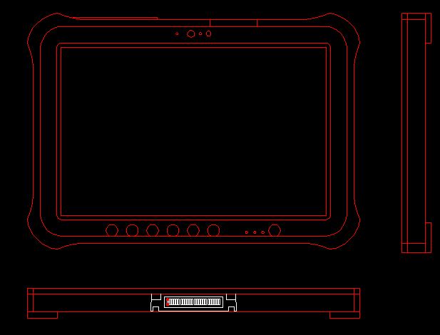
as far as the dock connector, we still don't have an off the shelf solution? They they seem to be 1mm contacts on 1.9mm pitch.
I really would rather not fab a custom pogo pcb if I can avoid it.
Also, I have a scale 2d cad drawing that I made/verifiedAttached Files:
Shawn likes this. -
-
Not sure if I’m on the right thread, but can’t seem to find anything else related to cmos battery removal to clear bios on a FZ-G1 Toughpad.
Sorry if this isn’t the right place. -
If you are trying to remove a bios password, it won't work.
interestingfellow and Shawn like this. -
FZ G1 tips, tricks, mods ?
Discussion in 'Panasonic' started by Shawn, Oct 4, 2017.