Just unplug the fan, that should be close enough.
-
-
How were you able to get the fan header to work might I ask?
-
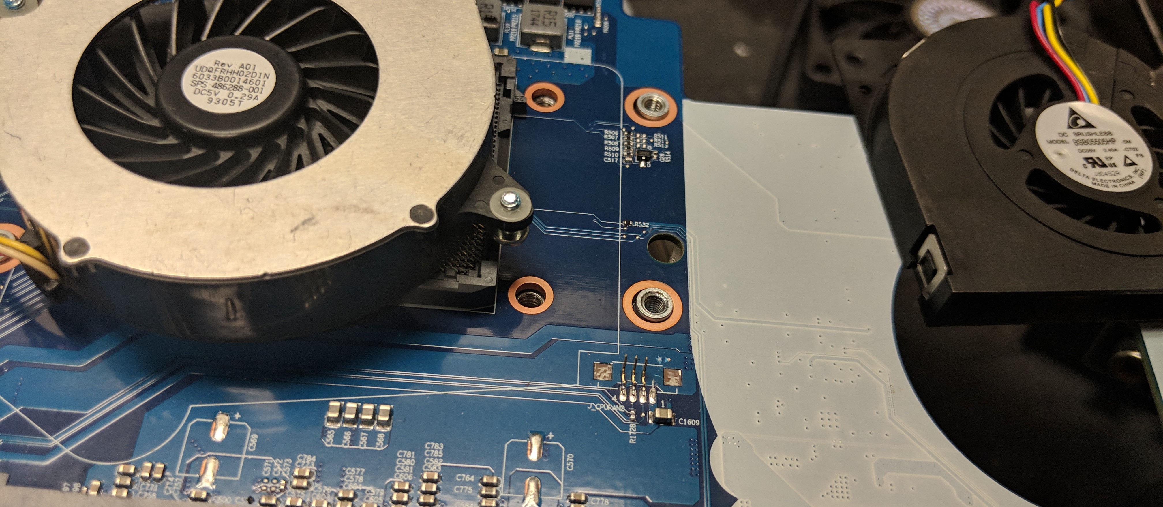
All I had to do was repin the PWM connector on the fan to match the pinout of the header on the motherboard - strange that it is not the standard configuration.
Eventhough the ESM lists the header as being "PWM" the PWM signal is at 100% duty cycle regardless of the fan speed settings set in software when hooked up to a scope. I'm wondering if this is why Clevo didn't include this fan - because the PWM circuit doesn't function correctly (I haven't dug into it enough to figure out exactly what's going on).
But if you find a quiet enough fan or don't care about the noise, it doesn't matter.Papusan likes this. -
I believe it's just the default the system is set to since the decision not to include the fan.
-
Only reason I ask is ,And take this as a warning. I've burnt up 2 motherboards with use of that fan header. I can attest that the fan you listed will work. But for how long your mother board will - I can not guarantee lol. Yours may work until the end of days. Or like mine, a week or less. Lol.
$400x2 = sucks for motherboards lol. -
Can you elaborate? How did you wire it? What were the symptoms?
-
Ouch, that sucks.
-
$400 is cheap. Even $400x2

Encryptonite, aarpcard, Cass-Olé and 2 others like this. -
Been looking through the schematics, can't figure out how anything could get fried unless something was wired up wrong.
5VS_2 is rated for 6A. In the models with 12V fans, the only things on the 5VS_2 rail are the keyboard backlight and the 5V PWM CPU2 fan header. The fan draws 0.4 amps - no idea how much the backlight draws, but I'm sure it's piddly. No way would that rail get overdrawn.
There's nothing special about how the tach and PWM signal paths are designed. The tach goes through a demultiplexor and then to the main EC. The other channel on the demux is the main cpu fan tach.
The PWM is supplied directly from the main EC. That chip actually supplies PWM signals for a variety of things.
Maybe there's an issue with the 4th PWM channel on the EC - maybe it's just safer to leave the tach and PWM on that header unterminated. . .Arrrrbol likes this. -
I'll pose this question. Who supplied your Bios ? As I have seen a few things that would have allowed for such problems. Especially given one bios , which was what came on both Mobo's from the seller lol. 3rd Mobo I didn't play with the fan header anymore until I was able to source a much better bios. But then I had already printed a new fan shroud that allows the stock fan to utilize that second small fin stack.
Voltage to said fan header on those two mobos exceeded 5v lol I can tell you that much. That 2nd fan idea was neat. But if you were to extend the distance of the bottom chassis to allow for a bigger fan with a better cfm rating, given the size of the fin stack , the results were within a margin of error due to heat soak of the fan being on top of the CPU bracket itself. Moving air across the entire CPU package and the fin stack netted much better results. Just an idea to toss out there to ya. With the way @Papusan has modded his notepals which is the same way I have all of mine. I can damn near force that little fans CFM if not more through that fin stack via the bottom of the chassis through the mesh with the laptop cooler.
I even sourced a few custom fans, and even printed off my own blades, used a handful of Delta's, sunons you name it. I vested alot and I mean alooott of time into that tiny fin stack of death with testing. Shimming, liquid metal, a new fan shroud netted better results.
Soldering a Bitspower to the heatsink itself. Then liquid metal between bottom of IHS and on die with the patience of a saint has so far netted the best results.Last edited: Feb 4, 2019aarpcard likes this. -
My bios is the unlocked Eurocom bios. I haven't measured beyond 5V to that header . . . I'm not sure how you could get higher than 5V to that header without a hardware change - the voltage isn't controlled by the EC. I could see a bios flash perhaps enabling/disabling the PWM output from the EC, but not the voltage on the 5VS_2 rail. I'm gonna risk it and see how it goes . . . I don't see anything in the schematics that would result in an issue. I'll definitely report back if anything happens.
Just to confirm, when playing with your fan did you repin it to match the pinout on the motherboard. The motherboard connector is not the standard PWM pinout. Plugging in a fan that is not wired to match the pinout could send 5V to the tach or PWM pins on the EC would could fry it. -
I would be interested to see said schematics you speak of. As you say 5v per schematics. I've seen higher and or lower across different motherboards per "unlocked bios" some where within this massive 300+ page thread it's discussed as to how the fan headers are handled per what voltage. ""
older fans with 3 pins, like my dell xps m2010 control via 3rd pin/wire so 5v/grnd is strictly for power, but clevo on these DTR control via 12v/grnd by lowering 12v to like 6v or something, 3rd wire is for sensor reading only apparently"" per a discussion a few hundred pages back lol
I know with one bios. That fan header in fact allowed for 12v. As the current fans within the laptop could have been powered by it. And EC may or may not control it. But there is indeed a way to change values of that header. Which leads me to believe you might have something rather different going on, and if it's not the exact fan that is installed Adda per the spec of it in the other 3 ports. It should beep like a nuke code inititaion is going down .
And yes, fan pin outs were correct. Also with the Eurocom unlocked bios. Be weary of what voltage you see within the bios itself.... I'll leave that there... and also, plugging something into that header is warranty void if it craps the bed , yee have been warned fellow brotheren . Lol -
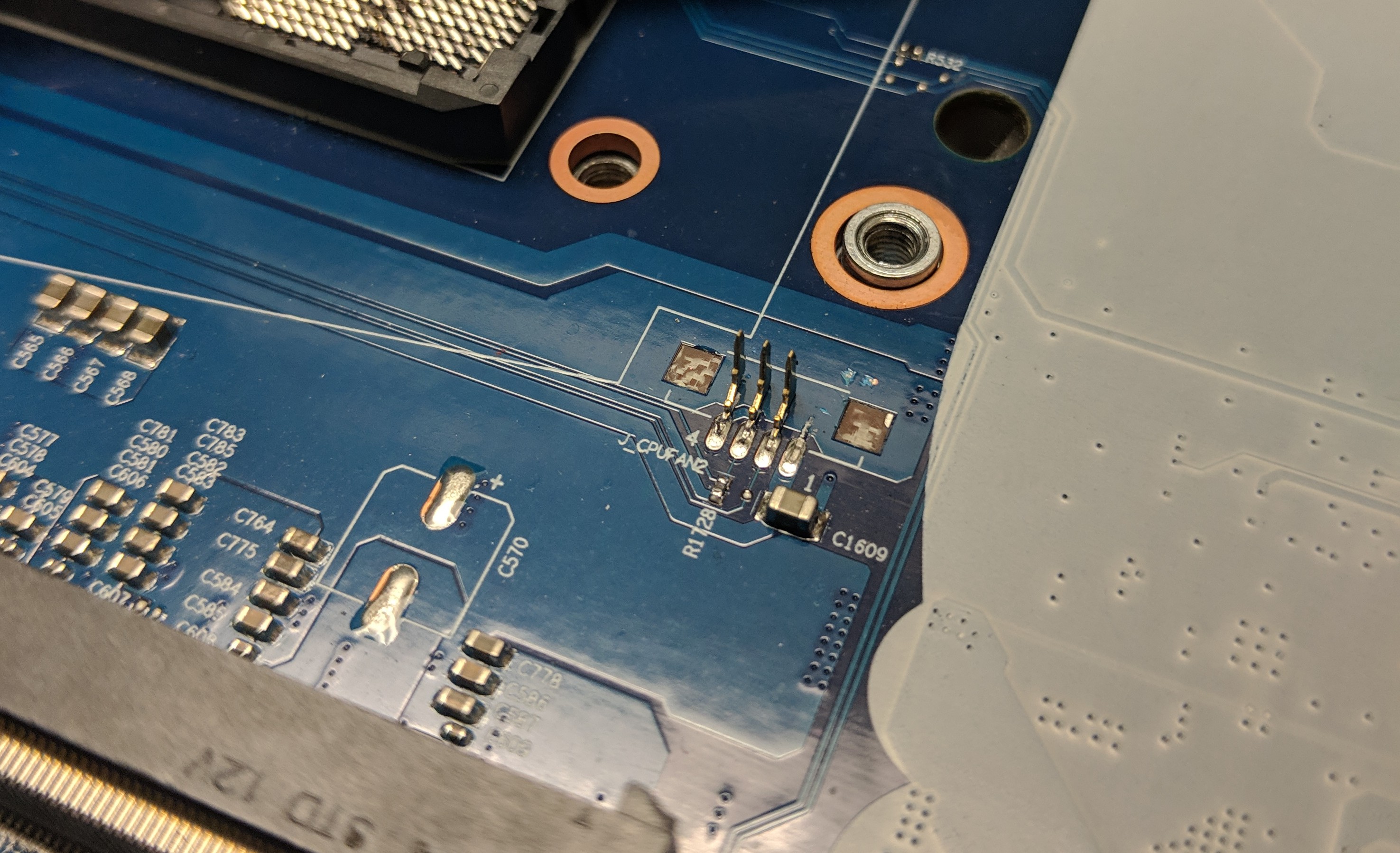
Here's everything that is connected to that fan header - I've added my own green wires to highlight the connections between sheets . . . . R1724 doesn't exist in my laptop. 5VS_2 is generated by PU7 directly from VIN - it isn't controlled by anything. The only other thing 5VS_2 powers in the P870TM1 is the RGB keyboard backlight. That won't function on 12V. I don't see anything that could make 5VS_2 go to 12V. Also if R1724 did exist, then it would back-feed 5VS_2 and destroy the RGB keyboard backlight.
U28A (IT8587) is the EC. It has at least 4 PWM channels - one of which is hooked up to that header. . . yet the EC seems only programmed to hold that channel at 100% duty cycle. Theoretically a bios mod could change that behavior. CPU_FANSEN is just the tach signal to the EC. FANSEN_SEL is the control line that selects between CPU_FANSEN1 or CPU_FANSEN2, and VGA_FANSEN1 or VGA_FANSEN2. It is also controlled by the EC connecting to pin 82 (I forgot to draw the green line, but you can see it.)
I can't see anything that would cause a problem. Maybe GPA4/PWM4/5VT is faulty on the EC - maybe this is why Clevo didn't populate the fan. If that's the case, then you can just not terminate pins 2 and 3 on the fan and just have it run at 100% directly from 5VS_2.
Hope I don't come across as argumentative - just trying to get to the bottom of this. If I've missed something I'd love to find out . . . for the sake of my MB lol.
EDIT: I also put a scope on pin 7 of U51. FANSEN_SEL is pulsed low to high at about 1hz. The EC is polling the tachs of each GPU fan and each CPU fan once every second or so. That seems to be functioning normally. Only odd man out here is the PWM signal from the EC, which is likely controlled in firmware.
![[IMG]](images/storyImages/EnZ03CI.png) Last edited: Feb 4, 2019lsflp, Encryptonite, Rahego and 3 others like this.
Last edited: Feb 4, 2019lsflp, Encryptonite, Rahego and 3 others like this. -
I don't take it as argumentative my good man. Nothing at all like that. I'm with you On the getting to the bottom of it. For the sake of your board too LOL. That was an absolute pain in the *** going through all of that for no more than what it was during my testings . I did keep one of the boards just in case though . I wonder if there are any revisions or differences between boards 1-2 vs what you and I have now. Especially given you are running a 9900k on yours I'll pull it out tomorrow and get to looking it over.
I'm with you on wondering that PA4/PWM4/5VT could be wonky. As when the first board let the smoke out of itself. The header itself in better words disappeared. Like there were only 3 pins sticking out of the board. No connector lol.
I have pondered going the route of using the un-used sata power connections I have available to power a fan. Just to avoid that header period lol. That's the most expensive fan header I have ever came across LOLLast edited: Feb 4, 2019Encryptonite, Papusan and aarpcard like this. -
Do you have a picture of the burned connector? I'd like to see it if you do.kfxsti likes this.
-
Did you do any kind of multimeter probing on the failed boards?
-
I'll snap a pic of it when I get back home for you.
And @Meaker@Sager I did not. I was super pissed given what had happened.Papusan likes this. -
-
@aarpcard
Attached Files:
Encryptonite, aarpcard and Papusan like this. -
-
The PCB looks really clean to have had something burning on it - makes me think something in the connector, not on the PCB shorted. I'm assuming Pin 1 pulled away and didn't melt. Can you measure R1728? Is it still ~4.7kohms?
The only thing I can think of is if that resistor failed to a short, then the Tach pin would be directly connected to the 3.3VS bus which could maybe overpower the sensor in the fan and cause things to heat up. -
The only reason why it was clean because we cleaned it trying to see if there was any damage to PCB itself as well. Lol, a pop and poof, and beeps << in that order lol . Then followed by me yelling obscenities .
Encryptonite, raz8020 and Papusan like this. -
Not just clean, but no signs of heat damage at all. If something shorted on the MB and got hot enough to melt the connector, there would absolutely be scorching on the MB. Considering that Pin 1 is missing, I wonder if it shorted to Pin 2 within the connector. That would explain damage to the EC, by feeding an unrestricted 5VS_2 into the PWM output of the EC.
I looked back through the thread. Can you clarify the above? How did you plug a 3 pin fan into the 4 pin header?Rahego likes this. -
Metal conducts heat pretty well, you not only need heat but a large amount of thermal energy to cause things like delamination of the PCB.
-
I'd have to actually sit down and ponder how we came about that man. I have hard time remembering what I did this morning much less that far back LOL.
I do remember that we moved the pins around within the fans plug . To what order and which fan I can't remember. As I have probably tested 20-25 different fans and between 10-15 different heatsink combinations.
I'm looking for the 2nd board right now as we didn't clean it and it still has charred remains. @Meaker@Sager that one does have damage to the PCB board.
@aarpcard is there anyway that you can find out what the max SATA power draw can be on the board ? -
Each SATA port has it's own independent supply. Schematics say each is rated for 2.5A. I wouldn't try to draw anywhere near that much current though. I'd say about 1.5A per supply would be safe for continuous use.
Any word on R1728? Also pictures of the 2nd board could be useful too. Thanks man! -
We are trying to find it lol. It's somewhere in this house . It was just to try and power probably a .80a fan . I'm trying to get temps that equal my current setup but with out having to use the spacer kit I made for the bottom chassis lol.
Just as soon as I get my little ones settled I'll measure that for you my good man .aarpcard likes this. -
So Here is my 'look at me everyone' moment. I am going to take it to the phoenix 5 thread
") Last edited: Feb 6, 2019
Last edited: Feb 6, 2019 -
Just remember there is no 12v sata in mobile platforms.aarpcard likes this.
-
I'd also be interested in seeing pics of your cooling setup. Might give me a few ideas.varunreeves likes this.
-
Seconded.! Also is there a separate page on nbr or elsewhere, where people post their modding videos ?
-
The overclocking section is the best for that generally.
-
Got tired of needing to use two outlets so I modded the AC cable. Not very impressive, but a big quality of life increase. Cable is rated for 10 amps. PSU's should draw no more than 9 amps.
![[IMG]](images/storyImages/CZV2Ie9.jpg) Rahego, kfxsti, Falkentyne and 1 other person like this.
Rahego, kfxsti, Falkentyne and 1 other person like this. -
Is the terminal in the splitter capable of the full load sustained too?
-
Yep, the spliced wires are interwoven and soldered, then covered in MIL-spec adhesive shrink. The boot itself is one of these: https://www.newark.com/raychem-te-c...-boot-trans-19-8mm/dp/36K3055?st=raychem boot
-
Good, nice one some of the "user adapted" cables I have seen on here give me nightmares.
-
@aarpcard @Meaker@Sager
I haven't forgotten my good Sirs. The flu is running rampant in my house. So Dr-Daddy is tired as hell lol.Papusan likes this. -
What is the maximum thickness of 2.5in drive that is supported? For instance, would a 15mm drive fit?
-
-
Thank you.
-
They are under the GPU so not much wiggle room on that.
-
Hello guys, I have a question. My laptop has 2x8 GB of RAM PC4-21300 which is rated at 2666 MHz but they run at 2400 MHz on my system, why is that? is there a solution for that?
-
Probably need to use XMP.
-
What's XMP?
Enviado desde mi G8441 mediante Tapatalk -
A profile that automatically overclocks the RAM, which some modules need to run at their full rated speed. Set it in BIOS or XTU.
-
I used the XMP default profile from the Clevo software rebooted and the system wouldn't boot, just a blank screen, I had to remove the BIOS battery:
![[IMG]](images/storyImages/2hmprnp.jpg)
maybe the parameters are wrong? -
Yeah all the subtimings are 0 for some reason. Did you try setting it in BIOS?
Also you don’t need to remove the CMOS battery, just hold Fn+D while pressing the power button. -
Thanks for the tip on the shortcut I had no idea. I tryed within the BIOS, but I get the same no boot issue. I think the problem is in the BIOS (or memory) itself. The voltage in the XMP profile is 0 V which seems off to me:
![[IMG]](images/storyImages/246pg0j.jpg)
The XMP profile is part of the BIOS or part of the memory module? -
What modules are those? -
I am not an overclocking expert by any stretch of the imagination, but I am curious regarding what you are seeing. Have you seen this post:
http://forum.notebookreview.com/threads/p870dm2-g-bios-throttle-question.801469/#post-10461305
Specifically, look at this bullet:
"The ability to run RAM with speeds higher than the standard 2133 MHz. I am not talking about overclocking here, I am talking about actual RAM sticks that are rated to run at 2800 MHz for example like the G.Skill 64GB 2800 MHz kit I have. With the stock BIOS, they will not run above 2400 MHz. In the case of the P870DM3, the stock BIOS now supports up to 2666 MHz. I believe but not more, so the Prema BIOS is a must again."
Question to ask is are you running Prema BIOS on your P870? -
FWIW I was able to run my RAM at 3000MHz using XMP on the stock BIOS.
*** Official Sager NP9877 / Clevo P870TM-G Owner's Lounge! - Phoenix 4 ***
Discussion in 'Sager/Clevo Reviews & Owners' Lounges' started by Spartan@HIDevolution, Oct 5, 2017.