i hate you
if one of the sets i had got from newegg worked like that i might be @2.4ghz right now...
too bad i couldnt even get the sets to even run @ 1000mhz Cas6... or even 800mhz Cas6 for that matter.
-
Ya there was a serious decline in that model at some point and it apparently never got better. They must have switched to much lower quality ICs. I was the first AW owner that I know of that got them right when they came out.
Makes me wish I had bought 2 sets now
-
OK, I'm starting to goof around with SetPLL at bit for my SLG (still not totally sure of TME unlock).
Questions:
1. Is there any editing that needs to be done to mypll.lut other than changing the "set bytecount=0xE" and adding the BCLK section as nando4 instructed here?
2. Is there any editing that needs to be done to setpll.rw after running setpll -preview?
I guess I'm not totally sure if the local0, local1 section need to be edited or if those should come out correct when the files are created. It does not match exactly to what setfsb shows in the diagnosis tab, but I'm not sure if it needs to.
TIA
EDIT:
OK, I think I misunderstood how to build the init section of mypll.lut. May need a bit guidance here. I'll keep studying. -
I got mine used off this forum, now I wonder if I got a good set. I havn't had any issues with them to date.
Havn't overclocked the M11x R1 yet, though I tried lifting the pin, but apparently didn't completely get it. Soldering looked like it was beyond me, felt like I needed three hands. When trying to lift the pin I think I started scratching into the mobo, but somehow the pin is still connected. Guess I'll get a magnifying glass with a light and take a closer look. On the plus side, the new keyboard is being shipped directly to me and skipping the whole need for a tech part lol. -
I think I got the init section right. I put [BCLK_B1] in the right spot. Still need to know what the set bytecount should be cause it comes up as 0x10. The other examples I can find all say 0x16.
Plus I only get a local0 and local1 (which do match setfsb) despite the fact that setfsb shows more (should be a local2 and local3 if they need to match). But that may be due to setfsb not officially support this PLL.
Advice? -
Sorry to keep bumping.
Take a look at the init section of mypll.lut written by setpll -read. Compare with what it "should" look like using what setfsb says in the diagnosis tab. I'm guessing I should not believe was setfsb says cause its not for this pll...I think...
mypll.lut
setfsbCode:[INIT] set bytecount=0x10 set Local0=0x0185E36FFFDD0306 set Local1=0x53E57D150D000000
So which should it look like? And what should the set bytecount=?Code:[INIT] set bytecount=0x10 set Local0=0x0185E36FFFDD0306 set Local1=0x53E57D1519A80100 set Local2=0x00000600AAAA0000 set Local3=0x14
Sorry for so many questions. I'm thinking this is not going to work. I re-did my solder job with smaller wire and it was good before assembly. B9b6 still did not change. Note sure if setfsb is inaccurate or if TME unlock is just not possible on SLG. -
I would set bytecount to be 0x16.
local2 and local3 can be left out, if you only need to change 2 bytes, just ignore local2 and local3.
But, I think SLG is different, I think you only need to change one byte for SLG. That is byte 14. If you go back a few pages in this thread you will see some more info about register 14. -
Right. I've got it set to change byte 14 to A1 (to try it at a bus speed of 275). So then if I only need the local1 and 2 with [BCLK_B1] replacing 00 with A1 under 0E, it should work but tries 5 times only to tell me it failed to set BCLK. Again I can't be certain tme is disabled, but the solder job was solid this time.
I don't fully undetstand the correlation between the datasheet and the bytes being changed. Register 14 (byte14?) Needs to be 1 to use a software control on bit 6:2 if I remember right. All of this is done just by setpll sending [BCLK_B1] to byte 14? I thought there would be more to it.
Its a bit over my head I'll admit. But with a bit more detail I'm sure I can get it. -
Try changing byte 14 (0xE) in setfsb's Diagnosis window with a value from the table here. Does CPU-Z report a change in CPU speed? If not then there's no point in setting up setpll as the PLL is not programmable while it's TME-locked.
-
I tried to use the apply button in setfsb to change byte 0E to A1. Doing this changed byte 0E from 01 to 81. But CPU-z showed no change. Setpll -read now matches byte 14 as 81.
-
If changing one byte using setfsb or setpll is all that it should take, then I can say the wire came off the pin during assembly, pin 14 does not unlock the tme on this slg, or software control of this slg is not possible.
Nando4 - your post with the insructions for setpll had another table with other bits detailed. Is sending one change to byte 14 is enough to line up all the bits you detailed? It just seems to easy. Thought it was more complicated. -
ok i am very happy to say, i switched 1hynix chip with a new samsung, and im 100% stable!!! at 1.73ghz pin mod thanks for all you guy's help. +rep for davygt
-
Well that means I was wrong about byte 14, I guess.
Looks like nando4 was right from the start, no software programming of the SLG PLL.
Thanks for testing that though. -
Good to hear. I was beginning to worry that if 1.73 wasn't stable I was wasting my time. Very encouraging.
nando4 -
Sorry I'm an idiot, but I think I'm starting to catch up
Your example has A1 equating to 275 MHz. But bit 7 has to be a 1 for SW frequency control to work at all, right? So it would need to be 11010001 which is D1. Stock 266 shows 81 because bit 7 is 0. That would show C1 if bit 7 was 1 for software control. Or am I way off?
The datasheet shows bit 7 is rw, but I can't change it for anything. I'm sure TME is still enabled meaning I have to open it up again to see if the microscopic wire came off or if we have the wrong pin/method for disabling it.
moral hazard -
don't give up yet. I don't know that TME is off. I'm sure that pin was soldered when I did it. But it did go through a 10K resistor. Thinking of putting another in place to make it 5K. Might need to be pulled lower?? -
If you've completely disconnected the TME pin from the rest of the circuit by cutting the track that attaches it then a 10K resistor is fine. If the TME pin is still part of the circuit and you wish to pull that point low then try a 1k or 100ohm pull-down resistor.
275Mhz requires byte 14 (0xE) to be 10100001b=0xA1 as shown in the table. You can put the bits into windows calculator using 'progamming' mode to verify. -
Thanks. I didn't cut the trace, so I'll have to look at that. Do we know where that circuit goes? Hope there's no harm in using a smaller resistor. But I think thats what I'll look at next.
Right, your example still has bit 7 as 0. According to the only SLG datasheet that mentions SW control at all, bit 7 has to be 1 to set frequency according to 6:2. 266 currently shows as 81. But that is because bit 7 is latched at 0. Maybe I still don't understand.
Sorry I ask so many questions and I really appreciate everyones help! Thanks for your patience. -
A byte's bits are labelled bit7 to bit0, ie: 76543210. So any number greater 0x7F will have bit7=1.
The reason a small resistor is used is because it then creates a voltage divider with a large voltage drop across the "unknown" part of the circuit and a small drop across the small resistor. The node point in between is what the PLL will sample on bootup. It must have 0.35V there or less to register as a logic 0, with a logic 0 disabling TME mode.
So I would suggest attaching a 100ohm resistor to GND from a pad/track or resistor leg leading off the PLL's pin14 as I did for my 2530P here. -
Yes I was looking at the wrong bit.
my bad. Good stuff as always, thanks!
-
Third time was NOT a charm. I tried again with 110 ohm resistor (what I had laying around). I can't get byte 9 to change from E5 for anything.
Maybe another SLG owner wants to try. At least prove the TME unlock. I'm losing my enthusiasm for sure. Thanks to all for the advice.
Now I see my wifi and caps lock icons don't light up. Maybe I missed a connection. Grrr.. -
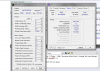
ok so im stable at 1.73ghz... ONLY because after boot i change the ram timings to 6-7-7-20, with memset 4.1.
heres a screenshot for you guys.Attached Files:
-
-
dont you think you might be maybe more stable with matched dimms? or at least just the one 2gb dimm?
-
well i might, i could try it and let you know =) im not so sure how stable the samsung stick is without the hynix in there but il do some testing.
edit: just did 3 runs of intel burn test on the 2gb samsung stick and all is well...so far. il test some gaming just to be sure. -
Sorry to intrude and you'd probably tell me to backread..but then it is 58 pages and I only have one question lol..So heres my basic question: Can't you just cut a pin in the SLG like the ICS and use setPLL to overclock? Cause I can probably cut a pin, not soldering a resistor or something is a whole different story..Thanks..=)
-
i want to say yes because it works that way on the ICS. but not sure if the TME has been unlocked on the SLG yet to prove this.
-
Is someone currently testing if TME can be unlocked by cutting a pin? has anyone tried it? This is the first time I've had the "urge" to overclock but the FSLx mod is kinda like skipping the "basics" of overclocking and jumping straight to the "advanced" section with hard mods lol..
-
a few ppl are trying the TME mod right now in the last few pages. i dont think anyone has been successful just yet.
to be honest if you have a steady hand the hard mod is pretty easy. I mean your cutting a pin OR soldering apin ether way right?
cutting pin2 in nonOC mode gets you a true 1.73ghz OR jumping pin7 in OCmode gets you 2.0ghz.
the TME mod(if it works) would get you the ability to figure out what the clocks inbetween(or above) work for your chip.
so in other words with the TME mod you can tweak around with the software to find your highest stable OC.
with the Hardmod you just pick one that works and stick with it. -
Ahh, hardmod sounds easier..I mean you just solder in the 10k resistor (like in the pic in your sig) and *poof it's 2.0GHz? Don't you have to change RAM timings or anything? Hmm..Well I have an electrician friend who has experience soldering..I trust him more than myself..BTW is that with OC mode on or off in BIOS?
-
yup. if your CPU and RAM can take the OC, thats all you need to do. you need to be in OC mode in the bios for this to work tho.
if your in nonOC mode your chances of booting are slim to none and you will have to remove the resistor to boot and change the bios to OCmode. -
No worries I'm always at OC mode..BTW we have the same RAM I think, so it should take the OC as well..no voltage thing mod was made right? The what do you call it type of OC mod?
-
yea this RAM seems to be solid!
i have done nothing else other than soldering the resistor like the pic shows. no volt mods etc. however i do know how to do a vlot mod(1.1v) if you need some more vcore for 2.0ghz.
i guess it would be called a FSLx mod. correct me if im wrong guys. -
2GHz at stock voltage SHOULD be easy for these CPUs. My Asus could do 320 FSB x6.5 at 0.95V pretty dang stable!
-
Ahh..yes I think I get the idea of FSLx mods..But the volt mod thing seems to be complicated..Good to know no volt mods have to be made, but in what instance would one actually have to add vcore and do a volt mod?
-
If you OC past the point of stability at the given voltage, more voltage COULD make it more stable. You are not always voltage limited though. Could be things such as chipset voltage, temps, cpu voltage, mem voltage, mem timings, etc
-
But aren't we all using the same laptop? So basically the same FSB,voltages/memory? So if 1 thing works for 1 person, wouldn't that mean it'll work for other m11xs?
-
No, because some chips will just OC better than others.
-
I've tried 4 times to no avail to unlock TME with a resistor mod. 10k all the way down to 50 ohms has not unlocked it. Unless someone wants to try cutting the pin and/or a dead short to ground on pin 14, I don't have much hope to unlock TME on the slg pll. Not that it cant work, but I was hoping for a mod that was fairly removable with little evidence left behind so I didn't feel comfortable cutting the pin just yet. I'd love to see it happen tho.
-
Well that just complicates things..Specially with a beginner like myself..
Ahh so PME unlock by cutting a certain pin isn't verified yet..So for now doing the FSLx mod is the safest since it also does not require any volt mods am I correct? Is there any way to get more than 2.0GHz by FSLx? -
Going beyond 2 GHz without adding voltage will most likely not be stable
The highest I could get my SU7300 in my Asus was 2080 MHz (6.5x 320) before it would freeze. I think I was able to validate it at 2112 MHz (325x 6.5) but it was pretty much useless there. -
Alright, will monitor this thread and hopefully you experts do good with what your all trying..As for me, if I ever get the guts to do the FSLx mod with the 10k resistor for 2.0GHz, i'll post pics or something lol
-
there are 3 more possible FSLx settings above 2.0ghz... but unless you have REALLY awesome RAM or know how to rewrite the Bios to remove the Cas6 lock you arent going to have any luck with them.
you only need to volt mod to get stability if you dont already have it. all chips OC different. no 2 chips are the same. some M11x owners will get 2.0ghz on the stock voltage, some wont even get 1.6ghz. its just the luck of the draw.
so in the case that you try 2.0ghz and arent stable you can "try" the volt mod to see if it helps get you stable. if not, you can try more voltage or just go back down to 1.73ghz or stock. -
I would love to just get 1.73 in OC mode and 1066 Ram....it is just stupid the way they have limited the OC mode compared to what it SHOULD be
-
Unless I'm mistaken (maybe some guy can comment) even 2GHz may be unstable without new memory or a volt mod. Its a bit of a gamble I think since every chip is different. That's why I was excited about a software overclock that can be easily changed to the point of stability. I still have hope, but maybe someone braver than myself can prove the concept cause I failed so far.
Some guy is the only one I know has accomplished slg 2.0GHz it but I also may try someday -
Would be interesting to dissect how ASUS are doing their turbo33 overclock. The m11xR1 is effectively doing a BSEL OC to 266, which locks it to [email protected] and sets the RAM ratio to 2:3. Asus maintains their x6.5 multiplier and can set voltages (up to 0.95V?). Only way the m11xR1 can do that is in non-OC mode, where RAM runs 1:2 ratio and hits walls far earlier than the 320Mhz that you got going.
Can you post a screeshot of the RAM details when running such a OC? eg: hwinfo32, AIDA, CPU-z. -
2.0 GHz is 6x 333 MHz
The ram divider gets changed to 2:3 since we are in OC mode right? So we are only looking at trying to run our ram at 1000 MHz Cas 6? I am still really surprised that so many kits cannot handle that. -
Okay now that sounds kinda scary..So if I do the FSLx mod and don't get good results, will I be able to just back out like get it back to stock? Cause I have no idea how to do a volt mod or how to increase voltage..so basically what your saying is when I solder the 10k resistor on the said pins, theres no way of telling what results I'll get? If it would be stable or not or what GHz I'll be getting?
-
I'll get a screenshot up for you when I get a chance, the 0.95V is the same whether stock or in Turbo33 mode and is dictated by the bios, the user gets no input.
Here is a link to a CPU-z validation I did on the Asus, maybe it can help. Also just noticed I was wrong about the voltage....my bad lol been a while since I OC'd this notebook
CPU-Z Validator 3.1
![[IMG]](images/storyImages/1401549.png)
-
Wow that Asus is at 2.1GHz..i wonder why it's so difficult for the M11x to get there..Sad really..
-
Well that is with SetFSB. WIth SetFSB how far have people gotten the ICS PLL M11x?
-
yup.
yup.
i am too... i have had SODIMM DDR2 run faster
yup, you just undo what you cut or soldered.
volt mod to 1.1v is just cutting a pin on a different chip under the heat sink, its not hard.
yup.
the Ghz is a set value depending on what pins you mess with. it does not change unless you change something with the pins. stability is the only thing that is in question. -
2.1Ghz
but most fall around 2.0Ghz give or take 100Mhz
http://forum.notebookreview.com/ali...ock-m11x-r1-slg-hardmod-only.html#post7049388
How to pinmod and further overclock the M11x R1 (SLG= Hardmod only)
Discussion in 'Alienware M11x' started by DavyGT, Jan 12, 2011.