I'm pretty sure it was clear that TME unlock is impossible on SLG, it's not programmable - unlike the ICS.
-
thanks guys for the suggestions, i think il just go the radioshack way. and hopefully find someone that can do this mod for me, like a camera repair place, or a pc repair shop. if not il go out and get the soldering iron some guy suggested.
-
maybe somebody can just bridge pin 14 to GND via 10K resistor....
-
Tried on my SLG. I tried 10K, 1K, 100, even 50 ohms to ground. Nearly positive I had the pin soldered good too cause I needed the iron to remove the wire. The only thing I didn't try was cutting pin 14.
Maybe someone who is a good pin-cutter can take a stab at that. Cut the pin and maybe add the 10K if necessary. I won't have my M11x open for a while I think. -
dont cut..... just ground it
-
why not cut it? im extremely good at that, i can have the 1.73ghz mod done in 5 minutes tops.
-
if you cut it, it will be very hard to resolder it back.......
-
I've done the grounding thing, via resistor. I wasn't brave enough to dead short it to ground.
ajslay, you're an expert pin cutter at this point I think. If you are up to it, give it a shot. Just look at the use of SetFSB in the OP to see how to check TME status. I can't see a scenario where that pin would need to be bridged again. Don't think that pin has any effect in the system. -
thanks =p im up for it, il do it as long as it wont have any harmful effects.
-
Ah, just do it anyway.... FOR SCIENCE! :yes:
J/K")
-
hahah =P maybe if i had a spare computer that was just as powerful. my m11x is my only machine. and it serves me well.
-
Well soldering to it had absolutely zero effect. And the datasheet shows that it is used for PCI-2 so I don't see where it would have any effect to cut it.
-
Hi guys my ram is stock 1066. Should I even attempt the 2.0ghz mod?
-
Your RAM should be fine.
I have a link to general pinmod questions in my sig if you interested. -
anybody know how to solder back cutted pin??
-
The same way you would solder anything else???
-
the problem is i dont have any flux....
i only have pre fluxed solder....
-
Slg here running at 1.73 completely stable. I amazing what the difference is in games between 1.6 and 1.73. Cant wait to try the 2.0
-
Been following this monstrous thread for a while, it's awesome what you all accomplished here.
I myself have an SLG and am contemplating the 1.73 mod. According to what I have read so far, by just disconnecting pin 2 from the chip activates 1.73? No software or any other steps required?
Excuse the noob question, first time pin modding.
-
Yup. you have to have OC mode disabled tho.
I made a general info post to help n00bs like you the link is in my sig. its like the Cliff's notes version of this thread.
-
The first time i was going to do the pinmod i backed out when i saw exactly how friggin small those pins are. I sugest the smarpest pointed blade u can get your hands on and a large magnifying glass.
-
Well that was an interesting lunch...
I turned on my M11x in the usual manner, loaded my 310FSB BAT file only for it to continue in a endless loop.
Checked SetFSB and my PLL is locked again (111 instead of 101). I can only assume that the pin has connected again.
Very frustrating as the drop in performance is easily noticable.
I will crack it open again on SAT to check but for the moment my new HD6950 is keeping me busy. -
Some times if 2 conducters are super close and the humidity raises they can close a circuit.
-
While correcting your TME-unlock consider bridging your voltage regulator VID4+VID3 pins to run at 1.1V as shown here. The extra voltage would give stability so you could get you past your current 310Mhz BCLK. Same link so has the more complex pinmod details to run at 0.95V or 1.0V.
-
hi nando.....
ive bridged back my pin 2 on my laptop and my clockspeed is currently at stock speed.....
i fail to overclock my t6500 to 2.79GHz......
ive tried everything and nothing works.....
maybe i need to wait for someone to unlock the TME for SLG -
Tried the 2.0 and failed, couldnt get the damn solder to stick to the pin,was burning the chip so decided to stop before i brick it...
-
Solder flux is your friend in this situation. Apply it generously on the items you wish to solder and the solder will stick.
-
For the 2 ghz mod which memory should I buy
G.skill , samsung, or kingston (not the hyperx)
these are the only firms I can get 1333mhz CL9
Thanks! -
For 2GHz mod you will need CL6 @ 250MHz. Samsung seems to have the best luck with timings.
-
some guy what g.skill dimms are you using?
-
http://forum.notebookreview.com/ali...m11x-r1-slg-hardmod-only-109.html#post7512814
Cant seem to open the link on my droid but thats the RAM i bought. -
Got the "super Kingston RAM" from Newegg and it ended up bricking my motherboard after having ran 2GHz successfully on stock RAM. I think this may be due to the fact the top DIMM slot was unable to "lock" the ram in place as it's slightly thicker than normal. I've got an ICS board now.
I performed the pin mod perfectly and SetFSB did not report the proper bit to change and unlock my PLL. I used a 10k resistor connecting that to a wire that wrapped around the screw to ground shown in DavyGT's guide in the start of this thread.
Does the pin need to be lifted and then soldered upon in order for this to work? I didn't have to lift any pins for my SLG mod. -
I tried doing the 2Ghz mod today and when I booted I got 7 Beeps when I disconnected the soldering from the SLG chip the computer booted fine
what is the problem? thanks. -
Please review the SLG pinmod info link in my sig. your question is near the very bottom (section 5).
-
HI I reviewed the info thanks! so just to make clear the only reason for the 7 beeps is that there are adjacent pins connected ?
-
I wouldnt say the only reason... but it seems that when i have bridged pins in the past it was very common to get random beeping from the PC. re-soldering the connection always seemed to fix the problem, for me anyway.
-
Well, I think I'm done, unless anyone can answer some questions.
For about 4 hours I was vacillating between having a heart attack from fear of another bricked mobo, and getting psyched up to try again. I have no idea how you guys did the ICS mod (soldering) I tried 3 different screw holes. I actually managed ONE BOOT where I ran SetFSB and it showed it was unlocked. Unfortunately it was a messy soldering job, just to test if it'd actually work with a particular screw hole that was miles away. When I went to implement it the right way, it didn't work
Does the orientation of the resistor have anything to do with it? If the resistor gets too hot due to the soldering iron transfer heat, does it die? Does the wire to ground need to have a massive contact area with the screw hole? The 10k ohm 1/4 watt resistor is what I should be using, ya? I'm terribly confused why this isn't working, my soldering points are solid, everything is connected and setfsb shows a dreaded E5 ;( -
Yes you can burn out a resistor if it gets too hot, doing so will make it an act like a cut wire - no flow of current
-
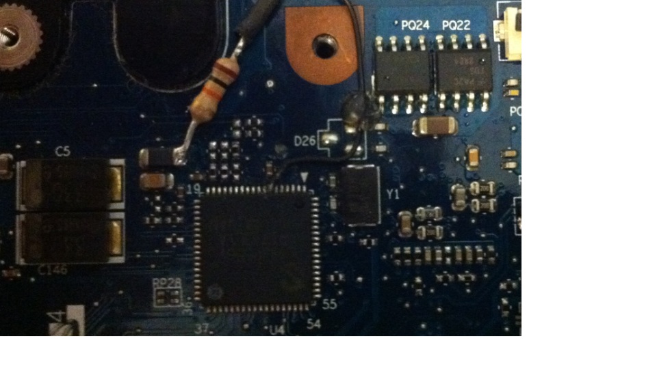
9 times out of 10 if something isnt right its due to bridged pins. DavyGT has a pic of what it should look like on the first post.
The fact that you got it to work and then resoldered then it didnt should tell you you had it right. you prob just need to try again.... trust me i do know how much of a PITA this can be. i almost threw in the towel my self. just try to scrape around inbetween the pins after you are done soldering with a hobby knife. it helps to remove any chances of conductive material bridging the pins. -
I think I may have burned out the resistor like the other guy said. I soldered on the pin about 10-15 different times, most the time it was flawless, no bridging, and the wire would not yield when tugged. I used two different resistors too. My first attempt at the 2 GHz SLG mod only took 10 minutes and I was up and running.
The ground soldering point is just the copper area around the screwhole, right? That's where I put it before when it worked. -
yea should look like this:
ImageShack® - Online Photo and Video Hosting
try using a new resistor -
Tried the 2.0 once again and ended up soldering a bunch of pins together
Afraid i bricked it. tried to undo what i did but was really unseccesfull. Now a question. Theres band new m11x motherboard on ebay for sale for 150$.
( NEW K1PWV Alienware M11x Laptop SU7300 Motherboard | eBay )
Should be fairly simple to swap it out no?? -
I was contemplating just getting an m14x but i love this little guy too much.
-
Its not hard.
Watch some youtube videos on how to take thw M11x apart.
What did you end up doing with the old mother board? -
I havn't bought the new motherboard yet, its still sitting here...
I'm going to try solder wick as a last resort to soak up any solder thats connecting pins. If that doesn't work i will buy the new mb. -
there are some videos on youtube on how to use solder wick. i have used it to fix my mobo before.
-
Ok , Guys I've tried everything I've re soldered cleaned the pins next pin #7
Added an ON\OFF switch.
every time I try to turn on the circuit I get the 7 beeps when I turn it off I can Boot normally but at 1.6 (Oc mode on).
Tried with 1066 stock rams each stick in each place or with hynix 1333cas9
didnt help.
added screenshots what should I try next???
BTW I've also tried Dave gt 1.05 bios and stock 1.05
Thanks!Attached Files:
-
-
The solder job looks good. if it were me i would try the 1.1VID mod next (click the SlG gen info link in my sig, read section 6a.) if taking the vcore up doesnt work it may be a chipset issue. sadly we dont have a chipset volt mod yet, as noone has needed it yet.
-
The 1.1VID mod If I cut the leg and the mod still doesn't work what are the risks?
If I do the 1.1Vid mod and set in bios to OC mode off will I be able to boot?
and Isn't the 1.1VID mod is for stability?
I couldn't post there was always the 7 beeps of the SLG failure.
Did your friends m11x beeped 7 times before the 1.1 mod? -
As long as you leave room to resolder the pin inbetween the cut, you can go back to stock vcore.
Yes. if the CPU needs more voltage to boot or get stable you would use the 1.1VID mod.
Im not sure what 7 beeps on the M11x means. i did have mine beep many times with the different pin configs i tried out and what always seem to fix " bootable" setting was draining the power out of the mobo and or pulling the ram. then hooking it all back up.
No his did not beep at all. just the board wpould power on but no post.
How to pinmod and further overclock the M11x R1 (SLG= Hardmod only)
Discussion in 'Alienware M11x' started by DavyGT, Jan 12, 2011.