
@uchihacg
bios password removal has been already succeded using hardware methods on this laptop, give a read at this page.
http://forum.notebookreview.com/del...ed-bioses-download-gpu-voltages-more-254.html
-
-
Yes I have been following this topic for quite some time but unfortunately, I don't have the means to do all this stuff, I just need a simple change for the bios (password doesn't bother me). Is it possible to do via the flash?
-
mmm, nope as far I know
however, thare are maybe some pay methods wich use the unlock code wich appear when you enter 3 wrong passwords.
I supose they calc a master password based on your unlock code and that will allow to enter setup and change or remove the password
anyway I didnt tested it. so your choice. -
No I meant is there any way for you to make it so that HT is off by default in the bios.wph file (just like you changed the voltages) so i can just flash the bios that way because its letting me flash new bios from windows.
Thanks for your help. -
Setup settings are stored in an nvram variable. You can potentially alter a variable from shell, but you cant do it from the update capsule because your laptops nvram will be a higher priority over the default-setup-setings nvram variable (which is being written to laptops nvram when you flash with /cvar flag). Technically its easier (not easy, just easier!) to alter the var in your laptop through shell than determine where the heck this is stored in the update capsule.
Sent from my GT-I9070 using Tapatalkcapitankasar likes this. -
This is a 10 second research on my Vostro:
HT enabled in BIOS ends up showing as the following under dmpstore NVRAM dump:
Whilst disabling HT ends up as this:Code:Variable NV+RT+BS '4FEE3D67-18F4-4217-BA7B-BC538148382A:DellVariable' DataSize = 41 00000000: 01 01 01 01 00 00 01 01-00 03 01 01 01 01 01 00 *................* 00000010: 00 00 00 00 00 00 00 00-00 00 00 0F 08 00 01 AA *................* 00000020: 03 01 00 00 00 00 00 00-00 00 00 20 01 00 01 00 *........... ....* 00000030: 00 00 01 01 00 01 01 01-00 01 00 00 00 00 01 00 *................* 00000040: 00
Pay attention to byte 0x3E .. it has changed from 01 to 00, indicating HT got disabled.Code:Variable NV+RT+BS '4FEE3D67-18F4-4217-BA7B-BC538148382A:DellVariable' DataSize = 41 00000000: 01 01 01 01 00 00 01 01-00 03 01 01 01 01 01 00 *................* 00000010: 00 00 00 00 00 00 00 00-00 00 00 0F 08 00 01 AA *................* 00000020: 03 01 00 00 00 00 00 00-00 00 00 20 01 00 01 00 *........... ....* 00000030: 00 00 01 01 00 01 01 01-00 01 00 00 00 00 00 00 *................* 00000040: 00
capitankasar likes this. -
Hey thanks, should i change the same 0x3E values to reflect my bios?
EDIT: Okay I've changed it and flashed it appears that wasn't the right one. There's no change in it.
EDIT2: I don't know what happened but all of a sudden my computer seems faster then before lol. -
.. what have you flashed anyway ?
I have no idea what is the length of DellVariable on L502x to begin with, on top of that I have no idea what position HT option holds in it.. you should rely on people who can get this information for you from their L502x laptop by performing dmpstore from shell (it has to be an interactive shell that reads entire NVS) in both cases - with HT on and off.
Then you fire up shell yourself and change the value of that entire variable swapping the corresponding byte that would be responsible for toggling the HT state. -
I've also spotted Setup variable changing ..this is with unlocked BIOS and UEFI enabled. The variable GUID is the following
So in the BIOS capsule look for HEX sequence of AB BA FB 4D 92 13 DE 4F AB B8 C4 1C C5 AD 7D 5D EE 39, the Setup variable starts withCode:Variable NV+RT+BS '4DFBBAAB-1392-4FDE-ABB8-C41CC5AD7D5D:Setup' DataSize = 307
00 08 00 00 00 00 00 00 01 00 00 00 00 00 00 00 byte sequence and is 0x307 (775 bytes decimal) bytes long as outlined above. You may see multiple occurrences of it though. One is meant to be set when flashed, the other one is meant for restoring default setting I presume.
HT disabled ...
HT enabled:Code:00000170: 00 00 00 00 00 00 01 01-00 00 00 01 17 17 00 00 *................* 00000180: 00 00 A0 06 02 00 00 00-01 00 01 00 00 01 00 00 *................* 00000190: 01 00 00 01 01 01 00 00-00 01 01 01 01 03 00 00 *................* 000001A0: 00 00 01 00 00 47 37 5F-01 05 0A 64 01 00 00 00 *.....G7_...d....* 000001B0: 00 00 00 00 00 00 01 01-00 00 00 00 00 00 00 00 *................* 000001C0: 00 00 00 00 00 00 00 00-00 00 00 01 00 01 01 00 *................*
Byte 0x17F changes its state.. and this is the byte you may be looking forward to swapping to the opposite inside the BIOS update capsule..Code:00000170: 00 00 00 00 00 00 01 01-00 00 00 01 17 17 00 01 *................* 00000180: 00 00 A0 06 02 00 00 00-01 00 01 00 00 01 00 00 *................* 00000190: 01 00 00 01 01 01 00 00-00 01 01 01 01 03 00 00 *................* 000001A0: 00 00 01 00 00 47 37 5F-01 05 0A 64 01 00 00 00 *.....G7_...d....* 000001B0: 00 00 00 00 00 00 01 01-00 00 00 00 00 00 00 00 *................* 000001C0: 00 00 00 00 00 00 00 00-00 00 00 01 00 01 01 00 *................*
but please note, the entire range (0x170 to 0x17F) doesn't necessarily come like that in the capsule, here's how it comes on my Vosotro A13 BIOS:
Quite different as you can see.. so you need to take the range from the capsule (the F33 subcapsule), find that 775 byte Setup variable, paste it to notepad or something and then label the byte rows to determine which is the byte that you need to flip.Code:00000170: 00 00 00 00 01 00 01 01 00 00 00 00 00 3F 00 01 00000180: 00 00 00 00 00 00 00 00 01 00 01 00 00 01 00 00 00000190: 01 00 00 01 01 01 00 00 00 01 01 01 00 03 00 00 000001A0: 00 00 01 00 00 47 37 5F 01 05 0A 64 01 00 00 00 000001B0: 00 00 00 00 00 00 01 01 00 00 00 00 00 00 00 00 000001C0: 00 00 00 00 00 00 00 00 00 00 00 00 00 01 01 00
Now, a request to @capitankasar, since he's the man with the tools (I'm the one with the plan hehe) and I've yet to complete my socket mod.
Would you mind testing something ? It would require 3 attempts to determine if this is indeed possible to override defaults upon reflashing the BIOS.
I had UEFI enabled in BIOS ( I also have a bunch of other options changed in BIOS settings, so thats why it will take 3 attempts) while taking the NVRAM dumps and comparing these dumps agains default BIOS settings have showed the following:
1. Byte 0x19C is 0x00 in BIOS capsule, while in my NVS its 0x01
2. Byte 0x1Cb is 0x00 in BIOS capsule, while in my NVS its 0x01
I would like you to patch the BIOS capsule flipping the first byte (0x19C is not a global address in the capsule, its individual to just that portion of capsule, the nvram variable that is) in Setup variable first then to flash it to the chip with /cvar flag. Then check if UEFI option would be enabled by default. If it does't then try patch the capsule again with just second byte flipped and revert the first one back, flash with /cvar again to see if UEFI boot is enabled by default. If it isn't then try flipping both bytes and flashing that.
There are also bytes which are 0x01 in BIOS and are 0x00 in my NVS, they are 0x2F (yes, two digits here, third row if you arrange rows by 16 bytes) and 0x174. Lets see if the first two make a difference and if they don't we try this pair instead. -
@kasar
I still have your valid dump from the time you bricked, so you can just reprogram the chip from the programmer and then reset your BIOS to defaults.
These are the lines that are important to us from your dump:
So the line you are looking forward in your dump is (it covers all occurrences, I've just checked)Code:00000190: 01 00 00 01 01 01 00 00 00 01 01 01 00 03 00 00 000001A0: 00 00 01 00 00 47 37 5F 01 05 0A 64 01 00 00 00 000001B0: 00 00 00 00 00 00 01 01 00 00 00 00 00 00 00 00 000001C0: 00 00 00 00 00 00 00 00 00 00 00 00 00 01 01 00
First you change it to:Code:01 00 00 01 01 01 00 00 00 01 01 01 00 03 00 00 00 00 01 00 00 47 37 5F 01 05 0A 64 01 00 00 00 00 00 00 00 00 00 01 01 00 00 00 00 00 00 00 00 00 00 00 00 00 00 00 00 00 00 00 00 00 01 01 00
Then in case first one fails you change it to:Code:01 00 00 01 01 01 00 00 00 01 01 01 01 03 00 00 00 00 01 00 00 47 37 5F 01 05 0A 64 01 00 00 00 00 00 00 00 00 00 01 01 00 00 00 00 00 00 00 00 00 00 00 00 00 00 00 00 00 00 00 00 00 01 01 00
And in case the two of the above fail:Code:01 00 00 01 01 01 00 00 00 01 01 01 00 03 00 00 00 00 01 00 00 47 37 5F 01 05 0A 64 01 00 00 00 00 00 00 00 00 00 01 01 00 00 00 00 00 00 00 00 00 00 00 00 00 00 00 00 00 00 00 01 00 01 01 00
Code:01 00 00 01 01 01 00 00 00 01 01 01 01 03 00 00 00 00 01 00 00 47 37 5F 01 05 0A 64 01 00 00 00 00 00 00 00 00 00 01 01 00 00 00 00 00 00 00 00 00 00 00 00 00 00 00 00 00 00 00 01 00 01 01 00
-
mmm , my motherboard socket is starting to get the plastic damaged due the high ussage, for that reason I stoped using it (also since I had less time for modding)
anyway, since I already have the descriptor unlocked and I can read or flash the whole chip from windows in just seconds using fptw64.exe included on the official ME tools package.
I will try if I can test something from there and leave the socket only for recovery cases.
I will try to create a dump using the fptw64.exe and then I will send you by PM, also due I didnt tested this read/flash method yet , and I dont know if it is stable or working (sometimes the backup data changes)jonnyhotchkiss likes this. -
Sure, hit me up. At any rate the most that can happen is NVRAM gets corrupted.
-
![[IMG]](images/storyImages/zhl8.png)
check your PMs for the dump")
-
@CaptainKasar
Wow! wow! wow!
I didn't know we can read/flash to whole bios chip from windows
You mean now that I also unlocked my descriptor, I can read/flash my EON bios chip from inside the windows?
That's cool if possible !!jonnyhotchkiss likes this. -
@Kpax7
exactly
and not only from windows 32 or 64, fpt have also DOS and EFI versions.
so the external hardware programmer is just needed the first time for descriptor unlocking or if your system becomes bricked and you need to flash your last working backup.
but yeah, if you want to be able to use FPT software for fast and direct flash writting or read, you need the descriptor to be unlocked.
here is FPT software for all mentionated OS
https://www.mediafire.com/?esr89opjitk65qk
I will also add it to the first topicKpax7 likes this. -
Or you could just override the lock by shorting the hda chip, fpt a chip dump, remove the lock and fpt the unlocked dump back to the chip. I presume no desoldering what so ever.
Sent from my GT-I9070 using TapatalkKpax7 likes this. -
yeah, that would be easier, however I dont know wich phisical chip and wich pin to bridge in the L502X.
also, if your firmware become corrupt and you need to flash your last working dump via a external programmer, there is no alternative to desolder and reprogram the chip externally.Kpax7 likes this. -
oh, some good news ^^
logo replacement has been sucesfully done by Kpax7
![[IMG]](images/storyImages/Photo4222.jpg)
I will ask him for the details to make my own version ^^ -
Its easy enough to locate a chip labeled ALC665 with a picture of a crab on it (Realtek logo). All Realtek HDA chips will have the same pinout, so it's still the ones we discussed before: DVDD (Pin1) and HDA_SDO or sometimes labeled SDATA-OUT (Pin5). Pin1 is the one by the dot at the bottom left side of the chip and chip marking facing the upright way.
It's true that if your chip ever screws up you will ned to desolder and reflash via a programmer... but it's also true that if you ever need to desolder you will have YOUR CHIP backup at hand (backed up somewhere safe, like Dropbox or Google Drive or something) and you could even build a programmer, get some chips, program them with a valid dump and have them around in case you ever need to desolder the chip. Thats my future project .. I still haven't done anything to it, even though I have SOIC sockets laying around.
In regards to our attempts in making the UEFI boot option (or HT option) be enabled by default.. I've kind of failed and started (and finished) another OSX related project. The funny thing about the last two dumps you provided was that they were almost completely different, the amount of offsets where diffs were found were just ridiculous.. So I have left this project hanging for now.
Cool to finally see people being able to replace the logo. When I was looking at resources (basically looking for format header in .efi modules via X-Search) I also found a stretched image saying "VOSTRO" in there, so this could also be replaced I bet! Waiting on details about this.. preferably on the bios-mods place, it's very lonely over there
Kpax7 likes this. -
well, I cant take the laptop appart now, and in the pictures I had from my old mods, I didnt saw any realtek chip, not sure if it there anyway, so if anyone have its laptop opened and he can take a clear / quality pic of the ALC665 chip, I will edit the image with the propper mods to be done and link it at the first topic
yeah, I noticed the dumps were different, not sure if it was cuz FPTW, however, when I flashed modifications through FPTW they worked fine while I was expecting it bricked my laptop.
but well, yeah, I also made some modifications in order if I can notice the difference with a dump with password setting vs a dump without password setting.
the differences were so many, so I coulnt find the proper parts to replace or edit in order to remove the bios password without use a completly new dump without password setting in order to remove the password.
I would also compare computrace on, select, and disabled dumps options in order to reset that setting from dump, but it seems the same history happens with the dumps, I dont know how they can differ so much after just rebooting the system and dont even edit bios options in setup.
relating bios logo, I will try to replicate what Kpax7 did, if I have success, I will post it in more detail
however, you can ask him directly if you dont want to wait since he was the first one wich had success with this
-
mmm, I had sucess, however, something definitly went weird
![[IMG]](images/storyImages/hkaf.jpg)
as you can see, my logo is working finally, however, some stuff is definitly weird.
take a look to Kpax7 image
the progress bar and F2 and F12 shortcuts images are there, however in my case, they are gone, that could be comprensible if I did something wrong, but ...... the intel logo is what really annoys me
where the heck it is being loaded? there are not a single intel image at the entire logo module!
what kind of sorcery is this?
-
My new motherboard also has energy star logo in the bottom left corner and Intel logo above F2 F12 text which I haven't found a trace of inside the bios. And I hadn't any of these images with old board... So they are definitely not in the update capsule...
Sent from my GT-I9070 using Tapatalk -
Haha :laugh:
@Kasar : Your boot screen looks more clear now
I think you made a mistake in finding the closing tag for the Dell logo and replaced your logo with entire "Dell log + Loading Bar + etc" and I say this because XPS logo is still loaded and that's before Dell logo! That's why you didn't remove that
But the intel thingy makes it look more official ^_^
That's still so weird ...
P.S> Closing tags for all of the images inside the Rom are the same so you should find the second one "FF D9"
Also I uploaded my Rom for analysis , take a look at. is in your inbox
Edit: I think I also found out the source to your magic intel logo
I think Dell used a black bar to cover the intel logo on the top in the ROM. And that's the 3rd image!
I'm now pretty sure that you replaced all your images in the Rom file with the Capitankasar logo
What size is your logo?
Actually it must be something between 7 to 13 kilobyte (approximately). I guess your file size must have been more than that!
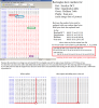
Illustration:
http://up.liz.ir/files/Bar.jpg -
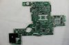
I heard someone wanted Mobo and ALC chip picture:
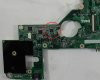
The whole Mobo at high quality:
-
oh, my image was 14,7 kb, smaller than the whole logo jpg image wich got extracted from the file.
I am going to try something different with a smaller image.
thanks for the images kpax!
so acording to all the info you guys said, I think this should be the instructions for the descriptor security override mod.
please, correct me if I am wrong ^^
![[IMG]](images/storyImages/4b73.jpg)
-
@CapitanKasar:
You're welcome!
@Timewalker:
This is interesting! How is the descriptor is related to the audio chip
So if we short those two pins for a brief second (with the cmos battery plugged ? or turned on laptop?) the descriptor gets unlocked and ready?
And also what recent tweaks have you done for OSx? The tweak in the bios for OSx sleep was awesome!
I'm now using Iatcos ML2, that's perfect. Lion was so annoying and troublesome .... -
Yeah, @kasar that's absolutely correct.
@Kpax7
You can use a 1K pullup resistor on there or just a paperclip bent at an angle, then power the laptop up. This bit of info came from Intel 6-Series Chipset specification (pp.91):
Also this, from intel ME presentation from a couple of years back:
In regards to OSX - I keep a thread up over at IM:
Mavericks on DELL Vostro 3450 & Inspiron 14R UEFI Clover - Installation Guides - InsanelyMac Forum
The recent work I've mentioned was this solution to solve the long dreaded problem:
https://github.com/Dolnor/EAPD-Codec-Commandercapitankasar and Kpax7 like this. -
Thanks for the nice info!
Guys like you are keeping insanely mac and modding community alive! I appreciate your hard work man!
one last question: Does those two pins need to be jumpered till the end of flashing/reading process or should I release the jumper after the boot up?
tanx -
Override is settled as soon as you pass the POST. At his point ME will not be initialized an FD security will be compromised. You can let go after Dell splash thing.
-
Logo change tutorial for L502x
There's a software called filescanner, get it here.
Open up the logo rom above with this! Then it shows all the JPG images inside the Rom, and shows each one of them and their boundaries in hex!
You must only replace the hex code of some sections of the Rom file. Otherwise you get a black screen.
Requirements:
a. A Hex editor like HxD
b. Basic knowledge of hex editing.
c. Basic knowledge of Phoenix Slic tool.
d. Custom image with these properties:
1. Grayscale (256color under test but not verified)
2. res : 232x307 for Dell logo
and : 66x28 for XPS logo
3. size of the custom logo should be below 10KB
Made a logo and then replace these parts from the Logo with the original logo inside Rom.
Baseline DCT
Huffman table
quantization table
and finally Scan area
So open your Rom file in filescanner and remember the hex code of the beginning and the end of each section then open your custom logo in filescanner and also remember the start and end of each section.
Then open both the rom file and logo in a hex editor and search those addresses and replace each section with that of the custom logo!
Both huffman and quantization tables of both logos are usually the same size! (have equal number of bytes) The only difference is the scan area of those logos.
So you must make a logo with equal or less size than the Dell logo. making equal is nearly impossible, but try to make a smaller logo in size and fill the end of the file with zeros until they get equal.
Here's a more illustrative example:
Then repack the wph file with the new Rom and flash.
Good luckRedScorp, jonnyhotchkiss, timewalker75a and 1 other person like this. -
thanks for the guide kapax
well, I had some issues with the images to get the tables match with the ones from your image and the module
but I think I finally got it to match on size.
photoshop, same heigh and width, grey scale.
then "save for web & devices" option
jpeg
low (quality 10) this is important, else the huffman table had different size.
now the sizes and stuff while hex editing seems to be fine, anyway had to add some zeros to fill the scan area like you did.
![[IMG]](images/storyImages/8yxi.jpg)
I am going to try now to reintegrate the logo module and build the bios to be flashed, lets hope it fully works at this time without corrupt the other images ^^Kpax7 likes this. -
yay! success
![[IMG]](images/storyImages/7y75.jpg)
custom logo time!
here are the addresses from the 0C7F41A9-0A6F-43F6-A0D9-1E2D01DBD7BE_4_1122.ROM module for the main logo image
Baseline DCT
from 9f5h
to a04h
Huffman table
from a8eh
to ba7h
quantization table
from a08h
to a8ah
Scan area
from ba9h
to 44abh
edit: those offsets may vary, since I worked directly over the modified Kpax7 logo module
I owe you one Kapax7
PS: now I miss that intel image, hehehe
edit: added the descriptor pinmod override instructions to the first post.Kpax7 likes this. -
Wow!
Nice Logo there!! Congrats!
I learned all of this from you, I owe you
While you're having success I should report that testing with a 256 color logo failed with a black screen
So I have to use the old grayscale logo ....
Maybe that's because you can't officially make a 256 or 16 color jpg !! I down sampled a jpg to 256 and no success -
I'm thinking of a new challenge :laugh:
Now that we changed the logo, what's next!?
Give me a new evil plan haha -
Nice work there, kasar. Most likely my vostro has slightly different offsets.. And i still wonder where energy star image comes from ...
We probably need to determine these setup defaults inside some module that is responsible for storing and restoring the config in nvram. Since you are the guys with a programmer you are labrats by definition, he he.
Something crawls my mind in the instructions though.
This is misleading.. because it says that you have taken the respective parts of the original logo and replaced this parts in your logo.. but in reality it happens the other way around? You take the respective parts from the logo you have created and hex edit them into the original logo in the module ?
Also, an odd thing i've noticed .. when you look at the original Dell logo it has a reflection at the bottom. When you export the image from FileScanner it suddenly loses the reflection and becomes a dumb oval logo.. just me?
Edit:
It seems like the nvram datastore is sitting inside PADDING-00350048_0_1199.ROM (searched for G7_ with XSearch) module .. it's a 191 Kb module on my Vostro.
Sent from my GT-I9070 using Tapatalk -
@Kpax7
well, sad the 16 or 256 color logos doesnt work, anyway I am more than happy with my black and white boot screen now
if you want new challenges, timewalker is now trying to change default bios setup values to enable UEFI and others, maybe you can give us a hand there
also, there was some aditional menus relating with overclocking wich couldnt be unlocked with regular hex editing on the advanced setup module.
timewalker and jkbuha said they are more related to the ME region, so maybe it could be posible to do something from there.
after some bricks, I sucesfully modded the ME region and relased a patch wich enable BCLK overclocking via software like intel XTU
but nothing else for the moment.
I wish I had something like overclocking menus in bios, but didnt had luck yet, even the overclocking strings are definitly at the advanced menu module
@timewalker
thanks
hehe lab rats, I like it
well, relating the intel or energy start images, I suspect they could come from other modules, like power management or intel video bios, however I have no idea at all.
and yeah, we made similar images on on photoshop (the details are back on this topic) and replaced some hex sections of the logo module with our image.
* Baseline DCT
* Huffman table
* quantization table
* Scan area
replaced those sections like Kapax7 said, and the logo is finally working
are planing to join also the custom logo gang?
oh and nice find!
Kpax7 likes this. -
I've used photoshop and mixed all the channels of the image to make a grayscale image, then exported it as an image for web with 70% quality optimizations, which lead to 140 byte haffman table (140 in my original dell logo too). The length of the scan area was about 1/2 of the original logo.. but the order of the sections of JFIF image i had produced was scattered. As in, in my image quantization table is before Baseline DCT, whilst in original logo its the other way around. I didn't bother looking much at it .. reintegrated and reflashed with PFlash.
I was at the point of tossing the laptop to the wall after it booted to a black screen and refused to proceed any further, even windows wouldn't start. On top of that the A13 crisis CD that I had around didn't work, good thing I had a stock-bios-based A12 CD at some place I didn't know where, so I spent a good 40 minutes looking for the damn CD. After reflashing from factory A12 it booted again.. I looked at the module that I have modded and reintegrated and the logo I've put in didn't appear at all, it showed up as an empty chessboard instead of an actual image. Second attempt was far more successful:
![[IMG]](images/storyImages/6LYue.png)
Update:
I re-did the graphics (not shown in the image above, its the old one) for Bios-Mods logo in vector form, then rasterized the image and weathered it to look more like an old gear .. the shadow dropping from a gear looks dull and doesn't really resemble anything. The image sure is sharp and bright (being all-white with gray-ish sides on some teeth).
Quite frankly, I like the original Dell logo more than anything, so I probably will revert to default image in a couple of hours. Or I'll make the classic blue logo a completely white and add some sort of wavy gradient to it .. whichever works.capitankasar likes this. -
nice job TW
hehe, yeah, those bios cd recovery cdroms also saved my lot of times
btw, what is that white square at the bottom left? -
it's supposed to be a shadow which renders badly when the image gets stretched by CSM driver
http://puu.sh/6M62c.png
Ah.. the bottom square - energy star logo which I have no idea where it comes from
P.S. Just to be clear - offsets for the respective sections of the image in Vostro's DellSplash logo are completely different.. Good thing @Kpax7 documented the procedure pretty involved.Kpax7 likes this. -
This sentence seems valid and clear to me
Anyway I'm not a native english speaker, so you know better
I meant to say: Make your own Logo , replace the mentioned sections in the original rom with the custom one.
I don't see any "energy star logo" on your screen !!
Am I blind or you're hallucinating? :laugh:
And also that's weird! The shadow mustn't get separated from the main logo! You sure you did everything right? The resolution and other properties?
I can't understand why the shadow converts to a white rectangle
@ Capitankasar
There were a lot of details that I didn't have time to talk about and you guys succeeded in finding them yourselves.
I forgot to say to use Photoshop , and save for web option and rastisizing the image
Perhaps Dell company used ACDsee editor for finalizing the Dell logo image and used Photoshop for creating the XPS mini logo (and probably Vostro mini logo) -
I mistakenly described the shadow first.. then I finally understood what he meant by "bottom square". The image is overexposed, hence you don't see the actual star in that image, but just a white rectangle
If you look very closely you can distinguish the familiar energy star logo in there.
The shadow is not being separated, it's just that the gradient at the bottom tooth of the gear is getting stretched and it creates an illusion of wider space, also the edges of the shadow are getting stretched and appear to vanish.capitankasar and Kpax7 like this. -
Made a couple more designs .. and didn't like how any of them look .. I guess you can call me a DELL fanboy then.. but I do prefer the vanilla logo that comes by default
![[IMG]](images/storyImages/6MrST.png)
![[IMG]](images/storyImages/6MrVM.png)
Also, made s sweet VOSTRO branding instead of the dull Vostro text and its too damn big to fit in terms of size in bytes, so i'm sticking with generic "Vostro" for now. boo-hoo
![[IMG]](images/storyImages/6MrNk.png)
I assume (I got fed up so not willing to test at the moment) the black bar is the bar that is getting filled by purplish-blue rectangles and doesn't act as a cover for the intel logo.. it somehow magically appears sometimes.Kpax7 likes this. -
Ok, then! Mr, fanboy
IMO anything better than the name of someone on my laptop! I prefer to put my own name instead of Michael Dell !!
We gotta do something about intel and energy star logos, I'm curios ! -
Guys with a programmer willing to partake in a test if UEFI bios can handle this op-rom bootloader? Supposedly it can boot the HDD caddy (optibay) while the original bios is unable to boot any OS from it, unless its installed as UEFI and a bcfg entry is pointed to a respective bootloader.
Plop - Documentation / Manual / Examples - Free Boot Manager, builtin usb driver, native usb, boot different operating systems, cdrom, usb, freeware, option rom bios
Because, lets face it, who uses PXE anyway ? Just swap out the network boot rom for this op-rom and see if it works ?
My bios has two oproms for Realtek NIC: Intel UNDI, PXE-2.1 (build 083) and again Intel UNDI, PXE-2.1 (build 083) .. GUIDs are 287AB657-3D8E-48FD-8FBF-6F69A3333098 and DA8B5CEB-5701-44B3-AA85-C38A5012FB44 -
Hi,
I installed the A10 Volt-modded 0.83-0.85v Bios for 540m on my XPS15.
Some history:
I own this XPS laptop for ~1.5 years now and it's my 5th (and probably last...) Dell system.
The XPS has given me graphics troubles from day 1.
Motherboard has been replaced on day 2 because the only thing that worked was the fan at full speed.
Actually, it's a very nice laptop and I can throw almost anything at it in terms of software and stress tests, and it works like a charm!
Strange thing is, however, that the only "game" I own crashes the system on default voltages and clocks within 15 seconds or even at loading.
Actually, I'm NOT allowed to call it a "game", because it's a dead-serious simulator.
It has been running OK on all my previous systems, the last one a Dell 6400 laptop with an X1400 graphics card. Frame rate was acceptable and it never crashed in 4 years.
On the XPS15, this same simulator is impossible to run with the factory default clock speeds.
I had some "intricate" discussions with Dell support over the years but my conclusion now is, that they have no clue how to solve these problems.
As long as the warranty runs they offer to replace motherboards, but as soon as the warranty expires, you're on your own.
I can't even guess how many hours/days/weeks I spent, trying to find a solution, talking to support guys, cleaning the inside of thermal paste that they seem to use by the gallon and reassemble the laptop properly myself.
On a positive note, I can now completely disassemble and re-assemble the XPS blindfolded!
The above mentioned simulator refused to run with higher core clocks than 571 and memory clock 802 Mhz.
Anything higher results in a crash, with sound loop and only the power button to recover.
Even with this 100 Mhz under-clock, the program sometimes did crash unexpectedly.
3 weeks ago I accidentally stumbled over this forum.
I read (almost-) all posts (yes, really!) and I now know that I'm not the only one with this problem on this laptop.
From my background, and previous experience (..), I know that patching firmware without the source code is a very delicate process, to say the least.
Therefore, my hat is off for the guys that have the courage and perseverance to start a project like this and to make it the success that it is today!
Yesterday, I finally took the plunge and installed the 0.83/0.85V modded Bios for the 540m.
I reset the 540m clocks to defaults (672/900) and started the "game".
It did not crash, but froze solid after 52 seconds.
I could ALT-TAB to MSI Afterburner and saw that the GPU temperature was 57 C which was not bad.
However, Afterburner had frozen at the same time and Task manager could not kill any frozen programs or processes.
Power off to recover again.
On re-boot, I noticed that for some reason the NVidia High definition Audio drivers were re-installed. (?) There are 4 of them and I didn't change anything in the configuration or cabling.
Anybody knows why thats happening after every crash?
(Btw. I use a large external display via HDMI)
Then, I lowered the GPU clock to 641 Mhz and, Lo and behold, immediately the simulator ran for 2.5 hours without crashing!
Temperature never went higher than 57 C.
After that I had a looong session at 650 Mhz.
Temp again went to 57 C and the machine idles between 47 - 52 C.
During this session the simulation froze once for ~15 seconds but then continued by itself (which is completely new!), so I guess 650 Mhz is as high as it goes.
That's an overall 80 Mhz improvement over the original Bios and the fan never runs at high speed.
I call that a great result and thank you for a great job!
My aim is by no means to achieve an over clock of the CPU or GPU.
The Intel i7 is more than powerful enough, and cranking it up in the cramped space of this laptop without adequate cooling, is asking for trouble.
But because I'm curious, I just downloaded the A12 modded 0.83-0.85 Advanced Bios.
Maybe I just enable Fast String, but leave the rest alone.
I'm perfectly happy and delighted with the current result!
Thanks again. -
I think the XPS15 outputs HDMI through the Nvidia card instead of the iGPU, so the audio drivers are automatically reinstalled by Windows when it reboots since the function is detected on the cable to trasmit audio?
You can also reduce the performance of your i7 by disabling cores or turning off hyperthreading. Since I only use mines as a media laptop now, I flat out disabled 2 cores in the bios which reduced idle heat by a large amount apparently as the fans don't turn on when its idling anymore. -
Thanks for responding,
Hiperthreading was one of the first things that was switched off 1.5 years ago.
The XPS15 indeed outputs to HDMI through the GT540m.
That's working properly for both video and sound, and temperatures on the 540m are even lower when the full HD monitor is in use than when the laptop's display is used instead.
But that doesn't explain why the NVidia High definition Audio drivers are re-installed after a crash, and only after a crash.
My fear is, and has always been with this issue, that as a result of the crash the Audio drivers or even the registry gets corrupted (remember the "sound loop") so that windows decides to re-install the drivers on the next reboot.
There may be more going on than the effects of a factory overclocked card or temperature issues, although the voltage reduction is a major step forward for certain software.
Fact is, I can run software that do not use audio and stresses both CPU and GPU to the max for days in a row on factory defaults, without a single crash.
It gets hot, but it won't crash. -
Hi capitankasar, and all the others reading through this post
as this is my first post on his website/forum,I will explain how I got to this forum and why I directly write to you.
First something about my laptop: (bought it in August 2011)
Dell XPS 15 l502x
Windows 7 64bit
Intel core i7
Nvidia GT525m
6GB RAM
BIOS version A06 (updated it to A12 today).
How I got to this forum:
I found it in a video description on a youtube video, where a guy had a problem with the same dell notebook like I have. The problem was that his screen froze while playing a videogame and he couldn't do anything but shutting it down.
He did all the good stuff like rebooting and so on and also updated his video if it worked or not. Then he found a mod in one of your forum posts for undervolting and this fixed it.
This is my story:
Like I already mentioned I bought this notebook in August 2011. I played games like Black Ops, World of Warcraft, Modern Warfare 2 and 3 without any issues. Now as I try to play World of Warcraft again, I get a problem I can't solve.
Randomly after spending some time in-game, the screen freezes in a randomly color (like green, orange, black, blue and so on) and I just can shut it down. The temperature is fine (60-65°C).
I rebooted multiple times, did update my drivers and lately also my BIOS. Nothing helped.
Now after the latest BIOS update, I thought that one of your mods may can help me too. Of course I want to make sure if this can possibly be a reason for the freezes. So it would be nice to hear what you think about it and how this sounds to you.
So this is the mod I thought about:
Current BIOS version: A12
GPU: gt525m
0.85v
0.85v
And this is the part where I hope you WANT to help me, because due reading through the forum and seeing all the posts and mods you did, I know you CAN.
So, what I hope you can do, is creating a mod that only needs to be flashed, without extra options because I really don't have any clue.
I honestly don't have any idea if this is much work for you or not. If you don't want to to this or if it is too much work, please tell me. I don't want to annoy you in any way.
Thanks in advance,
captainpanic -
Hi, would be nice if you can read throgh the text I wrote Thanks
-
@captainpanic
well, just flash the a12 advanced version with 0.85v/0.85v
with the stock settings, the modded bios is almost the original one, just stay away from the unlocked settings and it will be ok.
however the modded bios also offer pasive upgrades like intel video bios update and microcode update, so is recomended to install it even you run it at default settings.
dont worry
those bios are well tested and we have many tested recovery features ^^
I think most of people who tested them are happy and confortable with them
captainpanic likes this.
L502X modded bioses download (GPU voltages and more!)
Discussion in 'Dell XPS and Studio XPS' started by capitankasar, Dec 30, 2011.


