
quick questions... I know if my GPU has the prema bios if it says C3 at the end? I have driver versions 368.369 im using win 7 pro.. Is that modded driver you suggested to the other fellow better?
How come you are at 48x and your maximum volts dont even go over 1.2 and even at 42 or 43x mine reaches ALWAYS 1.3V ?
Also do you know what the shorter thermal pad covers? i know the longer one covers the vrm's but the shorter one?
![[IMG]](images/storyImages/BcC1R6D.jpg)
Sounds like clevo and all these new generation laptops shaving a few $$$ putting these flimsy ( for girly hands ) 15 inch keyboards on a 17 inch laptop :/ .. So used to my AW huge keyboard
-
-
That is the 4790k not the 6700k. Different machine. And that is 45x not 48x.ajc9988 likes this.
-
Better with smaller keyboard that still working ok than crippled performance, only 3 ssd slots, 2 ram slots, no G-sync and everything soldered on the motherboard!!! Maybe you also think the latest high end 6700Hq on top of this is better?
 Cass-Olé likes this.
 -
Can barely type with this girly keyboard :/ .. you cant tell me with all the extra space this thing has they cant fit a 17inch keyboard. come on now.
His picture says 48x not 45x
Last edited by a moderator: Jul 18, 2016Chronokiller likes this. -
Better Clevo use money on performance if they need to shave off somethings. Yeah. Would be better with bigger keyboard but performance is still the preferred!! You can use a external keyboard... But can you put better processor performance in a TurdBook?
-
![[IMG]](images/storyImages/44bb00f49d8aa399d9f1cbb9c600ec61.jpg)
No it doesn't. -
So 4,800mhz its not 48x then?
-
Where can you see 4800 in that ^^^ picture? I have problems to see everything on my little phone, but...ajc9988 likes this.
-
Im sorry im so fuming about my OC im even seeing numbers where there are non.. still at 45x my max volts reach 1.342 :/
Can anyone tell me what the shortest thermal pad is for?Last edited by a moderator: Jul 18, 2016 -
Umm where are you seeing 4800Mhz bud. I dont see anything over 4490Mhz.
Ditto. I cant find it either.Papusan likes this. -
-
The thinner one is for the components closest to the socket (and taller), the thicker ones are for the ones next to them (and lower).
-
I think it has been said several times that your voltage is too high. At 45x4 I can run the 6700K with stock voltage (meaning set to 0 "Auto" in the BIOS). I cannot remember now how low I could go with static voltage because I hardly ever run my CPU that slow, but I think it was like 1.175V and no offset. Somewhere in that ball park. That may help your high temps as well.
Look at the motherboard and you will see a row of components next to the phase blocks. I believe they are MOSFETs, but I don't remember now. They are shorter than the phase blocks. Anyway, the pad is for those little critters.bloodhawk likes this. -
Arent those the vrm's?
-
There are 2 rows of different components covered there. One row is Power Phases , the other row is VRMs or MOSFETs (never paid attention) , but both need cooling.
-
-
Look what I did today. Since I don't have any use for the 240W netbook AC adapter that came with the P750ZM (replaced it with 330W) I sacrificed it to steal the power cable from it and modded one of my AC-100 conveter boxes. Now it's got a full length cord on it. Seems to have no issues handling the high power draw with heavy overclocking. Cable doesn't even get warm. This makes it really convenient when I set up my little table in front of the portable AC unit. Don't have to move the AC adapters around or anything now because both cords combined are around 8 feet long.
Johnksss, bloodhawk, Chronokiller and 3 others like this. -
Nice!! Is it possible to get cable with that plug? I wasn't even able to find these plugs on ebay.
-
Nice job. You haven't a picture from the inside of the converter box?
-
why is J95 modding drivers for clevo based laptops?
-
brand of the machine doesnt matter, as long as the gpu is supported by the driver
Sent from my Huawei Mate 8 NXT-AL10Papusan likes this. -
Because he knows very well that Nvidia like to Cripple drivers Especially for older tech
-
@Mr. Fox
Do you think a dual BIOS mod like this will work on our system?
http://blog.jacksoftlabs.com/tag/amibcp/
I would be willing to give this a shot once i get the chance! (and time)Last edited: Jul 11, 2016Johnksss likes this. -
Easiest way to do dual BIOS is to remove your chip, do a total dump of the contents, duplicate it onto a second chip and then solder a socket to the motherboard.
-
But it wont be on the fly flip the switch implementation
Papusan likes this.
-
Are you trying to surpass Prema bios mod? Creating your own and <better> mod than @Prema next to? Have you the skills?
Or you bench with a lots of crashes and want push a new bench immediately
Just kidding bro
-
Haha, nothing like that , i dont have the right software tools for that. But the amount of locks up i have had stabilizing the voltage @ 4.8Ghz it would be helpful to have 1 BIOS with bench settings and the other for normal use.
-
Physical BIOS switches on laptops that move around, I can see that ending well
-
Or clock down to the new high end 6700BGA levels Maybe 6820BGA clockspeed can be reached without crashes
-
Can stick it in a small cut out in chassis
And use a LOT of electrical tape haha.
LOL no. Just one with adaptive profiles for 4.5-4.7Ghz for daily use and the other for straight out crazy benchmarking with static voltages.Papusan likes this. -
It would have been fun to change the cpu micro code, so that we could run heavy bench with BGA codes on our chips. Some would scratched their heads [email protected] GHz with +11.60 in Cinebench 11.5
Isn't so very fun with the newest high end mobile chips from Intel
 bloodhawk likes this.
 -
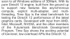
The motherboard already has a second BIOS pad right next to the existing one, and early prototype photos showed that. @Prema and I have discussed it and we are not sure if it would work correctly. What benefit would you expect from it?
You see the spare pad for it clearly in this photo, right next to the existing chip.
![[IMG]](images/storyImages/pch_bios.jpg)
New Sky Diver record for the P870DM-G platform until someone we know and love (a fellow named @Papusan) can beat it. @Phoenix... for the leaderboard, bro.
http://www.3dmark.com/sd/4176335
![[IMG]](images/storyImages/8QRzk2x.jpg) Last edited by a moderator: Jul 18, 2016
Last edited by a moderator: Jul 18, 2016 -
Well i was thinking of having one chip dedicated to bench settings and the other to daily use OC settings.
Second pad wont be needed for this switch. Since its a hardware switch that enables or disables one of the chips. So the BIOS will basically only see one chip at a time.
Though yes having 2 chips actually working at the same time and one as a back up would be awesome, but i doubt its going to work without some serious coding.Last edited: Jul 12, 2016Johnksss likes this. -
The socket is the forsure way to getaway with experimenting and not ever having to worry about bricking. But you will need a flasher/software and bios copies of your system. On the fly still needs to do a shutdown then power on and load new settings and then possible another shut down and reboot. Which the system would do on it's own.....Speculation of course.
Mr. Fox likes this. -
Agreed. I am about to order a flasher with clips, sockets and extra chips.
Dont mind the shut downs, its better to shutdown, switch and turn on than. shutdown switch and then resetup the normal settings every single time i feel like tinkering. -
Hummmmmm, that may not work totally as expected either..... I'll have to test that theory when i get a chance. to see if it holds the over clock after removing and then reinserting the chip.
Edit
Thanks to SVL7&Prema
Mine looks like this one.
http://www.ebay.com/itm/8-Programme...983874?hash=item1c66374a82:g:oAkAAOSwE6VXJoT6
But you can get one like this...
http://www.ebay.com/itm/TL866CS-USB...109481?hash=item1c531722e9:g:WlgAAOSwv0tVVxAv
The correct type socket
http://www.dediprog.com/pd/smt-sockets/SOK-SPI-8W-1
Buy a few chips like this one...
http://www.ebay.com/itm/like/251271621384?lpid=82&chn=ps&ul_noapp=trueLast edited: Jul 12, 2016 -
It might actually :
![[IMG]](images/storyImages/dualbiosdiagram.png)
The chips in this diagram are not from our system. -
The only down side is the fact that the chip is mounted on the wrong side of the mobo. It is a pain in the bottom to get to it. Granted, it's not something most people care to mess with and for most it doesn't matter where the chip is soldered. If the socket were mounted on a small remote PCB on the GPU/CPU side and connected by short wires soldered to the EEPROM pad that would work pretty sweet. If you have to tear the machine apart completely and repaste, at that point it makes little difference to me whether the chip is socketed or soldered because it's going to be a hassle to deal with no matter what. I'm thinking about doing the remote PCB mounted socket mod at some point, but probably not until I have a good reason to dismantle the beast. I already have the stuff I need to do that, but no incentive at the moment.hmscott, Papusan, Spartan@HIDevolution and 1 other person like this.
-
Or. Your bios has a section like the P570WM* where it saves the user settings(Meaning Your Overclock). Then you just reload them at will.
Also recheck my other post. I added some more stuff.
Edit:
@Mr. Fox . Yes, there is always that. totally forgot how hard it would be to swap out the bios chip. -
I've got exactly the same one as you do. Works really nice and that would be the one I recommend as well. Included in that kit is one of the small PCBs that could be used to mount the socket on the easily accessible side of the mobo.
Edit: I disassembled the crappy one I bought to fixed bricked LCD panels and use that connector assembly on the nice programmer now. Works really well. Has permanently mounted cables for eDP and LVDS connections on it. -
I bought that one because it also has the power plug on the other side of the programmer. Although not sure what to use that part on yet. LOLMr. Fox likes this.
-
Nice! Those are too high end for me. I ordered the normal USB dongle type.
Im just going to run the wires on the inside from the solder pads and mount things on that backplate with the HDMI cut, and have the switch poking out.Johnksss likes this. -
Nothing wrong with that! But I like to be able to flash my other 10 machines as well plus amd vga's on the fly.
What other parts come with what you ordered and how much was it? -
Ordered these 2 :
http://www.ebay.com/itm/EZP2010-USB...135451?hash=item4d44c35b9b:g:AgsAAOSwQaJXSBfH
http://www.ebay.com/itm/USB-Program...067575?hash=item41a2f87ab7:g:xA8AAOSwoydWlHd8
(Second is for kicks)Johnksss and Spartan@HIDevolution like this. -
@bloodhawk that schematic should work generically since it is using a SPI flash chip and pulling chip select pin high or low based on the position of the toggle switch.
bloodhawk likes this. -
Sweet. Yeah, just figured the same, after reading up a bit. Thanks for the confirmation.
-
General concept, lift CS pad from the SPI flash chip, piggyback your new SPI flash chip ontop for all pins except CS, solder wire to CS pad and all CS pins, and hook up like shown using the SPDT toggle switch, diodes, and resistors in the generic schematic. BTW I don't know if you noticed but P870DM(-G) service manual is available on the Clevo mirror now.
-
Yeap found it a while back on TI.
Gonna piggy back em and stick them to a small panel at the back. Will have to run wires from the motherboard.
-
http://prntscr.com/bs8165
See @Mr. Fox even at atock this thing goes over 1.3v -
Uncore at 4100 is not stock.....
And the stock voltage for that machine is wrong from the factory. And if that is modded bios, then you might need to set it at 1.2V and see how many multies you can go up from there....Speculation of course...
Clevo Overclocker's Lounge
Discussion in 'Sager/Clevo Reviews & Owners' Lounges' started by Spartan@HIDevolution, Mar 4, 2016.


![[IMG]](http://i.imgur.com/8QRzk2x.jpg)

